3 Product Description System Manual
14
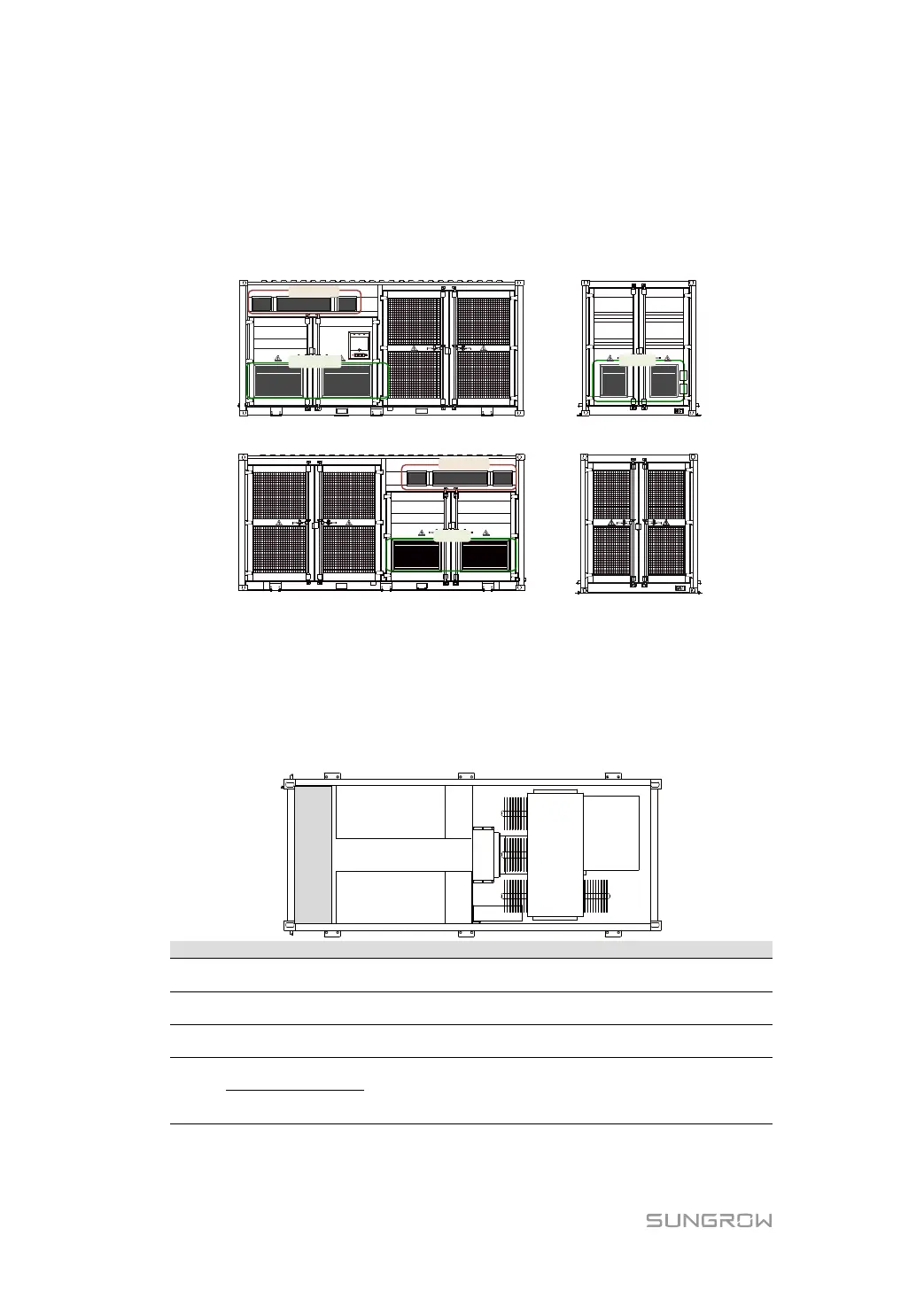
3.3.3 Ventilation Design
Six air intake grills (In-1, In-2, and In-3 in the figure below), located in the MV Station room,
are the entries of fresh air.
Exhaust air of the MV Station is extracted via Out-1, and Out-2.
Front view Left view
Back view Right view
In-1
Out-1
Out-2
In-3
In-2
3.4 Interior Design of the MV Station
3.4.1 Internal Components
The figure below shows the top view of the major electrical components inside the MV
Station:
DC cables connect to the corresponding area of this cabinet
after entering the MV Station.
All ports for communication between the MV Station and
external devices are designed on this device.
Convert the MV Station output voltage to medium voltage level
The two modules are of the same model;
Hereinafter the two modules will be referred to as #1 and #2
respectively
 Loading...