EasyManuals Logo

Supermicro M12SWA-TF User Manual

Supermicro M12SWA-TF
105 pages
To Next Page IconTo Next Page
To Previous Page IconTo Previous Page
Page #11 background imageLoading...
Page #11 background image
11
Chapter 1: Introduction
1.1 Quick Reference
Note: It is recommended that you connect both 8-pin (JPW3) and 24-pin (JPW1) connectors to your power supply modules
before powering on the motherboard.
BAR CODE
BAR CODE
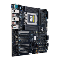
M12SWA-TF
REV:1.00
DESIGNED IN USA
BIOS LICENSE
IPMI CODE
MAC CODE
SAS CODE
DIMME1~H1
FAN5
SATA0
JTPM1
VGA
JWP1
JSPDIF_OUT
JPAC1
UID LED
J31
BMC LED
CPU SLOT1 PCI-E 4.0 X16
CPU SLOT2 PCI-E 4.0 X16
CPU SLOT3 PCI-E 4.0 X16
CPU SLOT5 PCI-E 4.0 X16
CPU SLOT6 PCI-E 4.0 X16
CPU SLOT7 PCI-E 4.0 X16
FANC
FAN6
FAND
CPU
DIMMA1~D1
JPW4
FAN4
FAN3
JWD1
FANB
FANA
JSTBY1
FAN1
FAN2
BT1
SATA1
JL1
COM2
JWP2
JSD1
COM1
JUSBLAN1
JPW2
M.2-0LED
M.2-1LED
M.2-2LED
M.2-3LED
JBT1
JF1
JPI2C1: PWR I2C
JOH1
USB 2/3
PCH_FAN
JAUDIO1
USB 6/7
USB 8/12
LAN 1
JPW3
JP5
JPL1
12V PUMP PWR1
JD1
SATA2
SATA3
USB 10/11
USB 9
USB 0/1
M.2 NVME
M.2 NVME
M.2 NVME
USB 4/5
U.2
JPL2
JPUSB1
LAN 2
JPW1

Table of Contents

Other manuals for Supermicro M12SWA-TF

Questions and Answers:

Question and Answer IconNeed help?

Do you have a question about the Supermicro M12SWA-TF and is the answer not in the manual?

Supermicro M12SWA-TF Specifications

General IconGeneral
BrandSupermicro
ModelM12SWA-TF
CategoryMotherboard
LanguageEnglish

Related product manuals