39
Chapter 2: Installation
2.7 Connectors
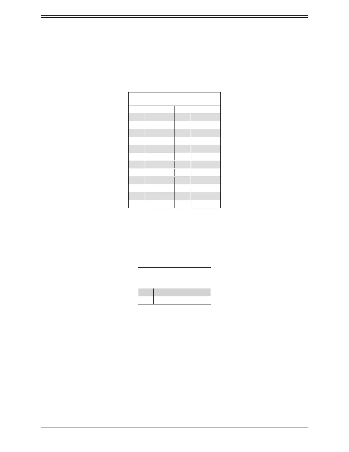
ATX Power Supply Connector
The 24-pin power supply connector (JPW1) meets the ATX SSI EPS 12V specication. You
must also connect the 8-pin (JPW2~JPR4) CPU power connectors to the power supply.
ATX Power 24-pin Connector
Pin Denitions
Pin# Denition Pin# Denition
13 +3.3V 1 +3.3V
14 -12V 2 +3.3V
15 Ground 3 Ground
16 PS_ON 4 +5V
17 Ground 5 Ground
18 Ground 6 +5V
19 Ground 7 Ground
20 Res (NC) 8 PWR_OK
21 +5V 9 5VSB
22 +5V 10 +12V
23 +5V 11 +12V
24 Ground 12 +3.3V
Required Connection
8-Pin Power Connectors
JPW2~JPR4 are 8-pin 12V DC power input for the CPU that must be connected to the power
supply. Refer to the table below for pin denitions.
8-pin Power Connectors
Pin Denitions
Pin# Denition
1 - 4 Ground
5 - 8 +12V
Required Connection
Important: To provide adequate power supply to the motherboard, be sure to connect the 24-
pin ATX PWR and the 8-pin PWR connectors to the power supply. Failure to do so may void
the manufacturer warranty on your power supply and motherboard.
 Loading...