IGNITION AND ELECTRICAL 3-3
OPERATION
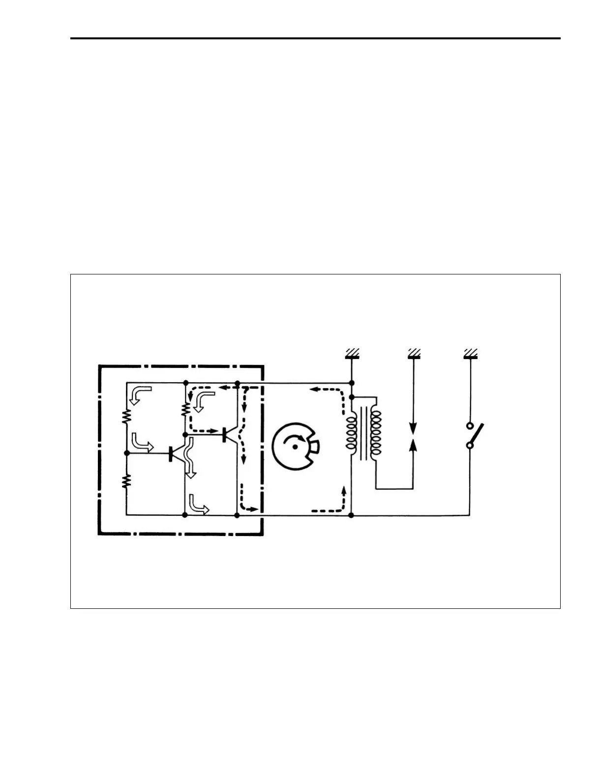
The transistorized ignition circuit will be discussed by referring to the diagram below:
When the recoil starter is pulled, the flywheel is turned. An electromotive force generated in the primary
winding (n
1) of the ignition coil makes the transistor (TR1) conduct through the resistor (R1) and forms the pri-
mary circuit (indicated by dashed lines).
As the flywheel turns further, the primary current increases, and the terminal voltage of the circuit consisting
of the resistor (R
1) and transistor (TR1) increases. This increases the working voltage at the connection of
the series circuit (R
2 and R3) connected in parallel to the primary circuit. As the flywheel turns further, the ter-
minal voltage of the resistor (R
3) in the resistor circuit (R2 and R3) rises to the level of working voltage of the
transistor (TR
2) when the ignition timing approaches, and thus the transistor (TR2) is turned on. As a result,
the base current of (TR
1) flowing through the resistor (R1) is by-passed, and the transistor (TR1) is turned off
from the conductive state.
The current flowing through the primary winding (n
1) is thus interrupted, and a rapid change occurs in the
magnetic flux across the ignition coil. The result is a high surge voltage in the secondary winding (n
2).
TRANSISTOR
R
2
R3
TR2
TR1
R1
FLYWHEEL
MAGNETO
IGNITION
COIL
SPARK
PLUG
EMERGENCY/
ENGINE STOP
SWITCH
S
N
n
1 n2
 Loading...


