3-6 ENGINE CONTROL SYSTEM
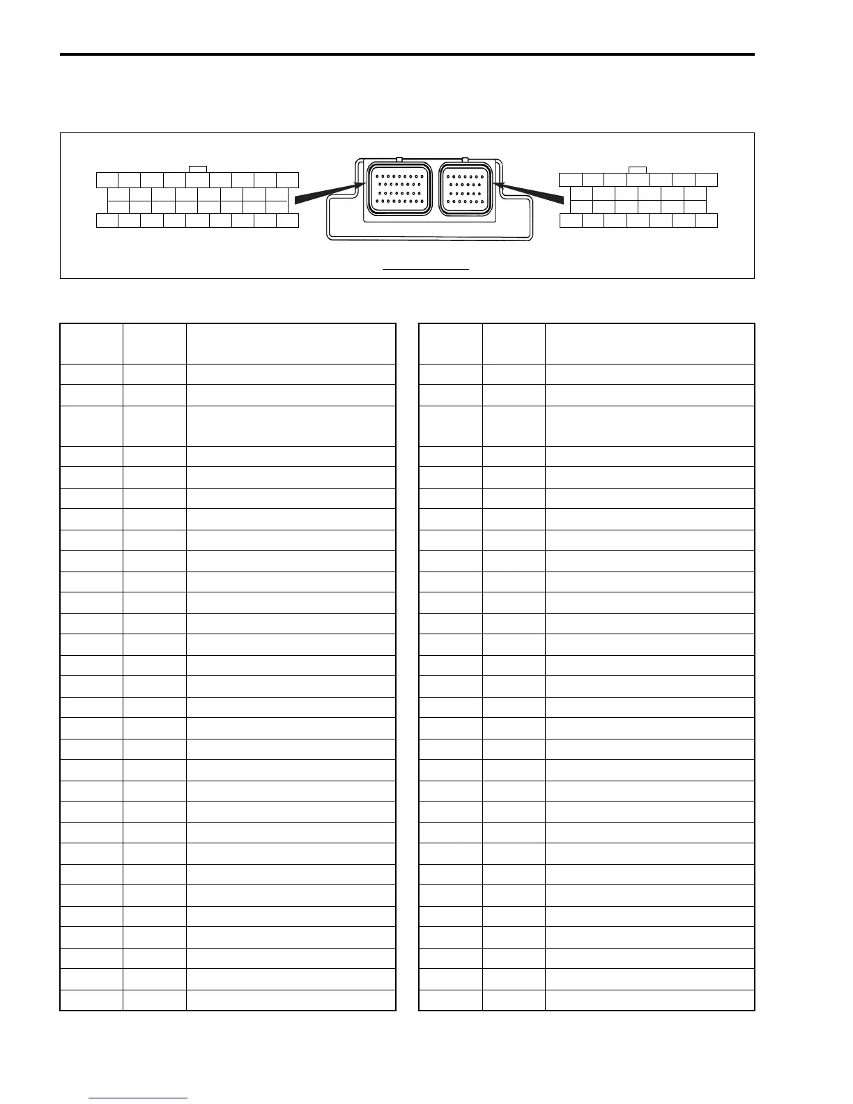
ECM CONNECTOR/TERMINALS LAYOUT
TERMI-
NAL
WIRE
COLOR
CIRCUIT
TERMI-
NAL
WIRE
COLOR
CIRCUIT
1 Dg Starter relay control 31 Br/R No. 2 OCV (–)
2 B/G O2 Feedback 32 O/W Purge valve (–)
3— — 33Gr/R
Variable intake control valve
(VSV)
4 R/B CKP sensor 34 P Rev-Limit lamp
5 Y/Bl CMP sensor #1 35 Y/B Tachometer
6 B/O CMP sensor #3 (VVT_ STBD) 36 B/Br No. 2 Fuel injector (–)
7 O/G CMP sensor #2 (VVT_ PORT) 37 W/G No. 5 Ignition coil (–)
8 V/W Ex-manifold temp. sensor #1 38 Bl/Y No. 6 Ignition coil (–)
9 Lg/W Cylinder temp. sensor 39 Gr/Y No. 3 Ignition coil (–)
10 G/R Ex-manifold temp. sensor #2 40 — —
11 P/Bl Shift position sensor 41 — —
12 W MAP sensor 42 O No. 1 Ignition coil (–)
13 B Model distinction (DF200 only) 43 Bl/W Buzzer
14 R Power source for sensor 44 B/Y Low pressure fuel pump (–)
15 Bl/R Emergency stop switch 45 Lg/R No. 4 Ignition coil (–)
16 Br/Y Throttle position sensor 46 B Ground for power
17 P/B Ground for ECM main relay 47 B Ground for power
18 Br Neutral/Cranking switch 48 B Ground for ECM
19 Bl Oil pressure switch 49 B/W Ground for sensor
20 Gr ECM power source 50 Bl No. 2 Ignition coil (–)
21 Y PC communication 51 Bl/B Oil lamp
22 O/Y PC communication 52 B/R High pressure fuel pump (–)
23 B/Bl Engine switch 53 Lg No. 4 Fuel injector (–)
24 O Buzzer cancel 54 O/B No. 1 Fuel injector (–)
25 Lg/B IAT sensor 55 W/B IAC valve #1
26 — — 56 R/Y IAC valve #2
27 O/Bl No. 5 Fuel injector (–) 57 W/Bl IAC valve #4
28 R/W No. 3 Fuel injector (–) 58 R/G IAC valve #3
29 Y/R No. 6 Fuel injector (–) 59 G/W CHECK ENGINE lamp
30 Br/W No. 1 OCV (–) 60 G/Y TEMP lamp
(FRONT VIEW)
27 28 29 30 31 32 33 34
36 37 38 39 40 41 42 43
44 45 46 47 48 49 50 51
35
52 53 54 55 56 57 58 59 60
123 45 67
8 9 10 11 12 13
14 15 16 17 18 19
20 21 22 23 24 25 26

 Loading...