3-28 ENGINE CONTROL SYSTEM
BY-PASS AIR SCREW/PASSAGE
Since the throttle valve is almost fully closed when idling/trolling,
the main flow of air necessary to maintain idling/trolling speed
passes through the by-pass air passage.
The by-pass air screw controls the flow of air through the pas-
sage and provides a means of partially adjusting the total
amount of air necessary for idling/trolling.
NOTE:
See page 2-16 for the by-pass air screw adjustment procedure.
IAC VALVE/PASSAGE
The IAC valve is a stepper motor type mounted on the collector
assembly.
Its purpose is to control the amount of intake air flowing from the
IAC passage.
The IAC valve consists of a stepper motor, rod, valve and other
parts.
As the stepper motor is controlled by signals from the ECM,
valve position changes will increase or decrease the air flow
through the IAC passage.
IDLE AIR CONTROL SYSTEM
OUTLINE
The ECM controls the position of the IAC’ valve to regulate a portion of the intake air flow to the collector
assembly.
This system is used for the following purposes:
• To keep idling/trolling at specified speed.
• To improve driveability when decelerating. (Dash-pot effect)
• To improve engine starting and warm-up performance. (Fast-idle function)
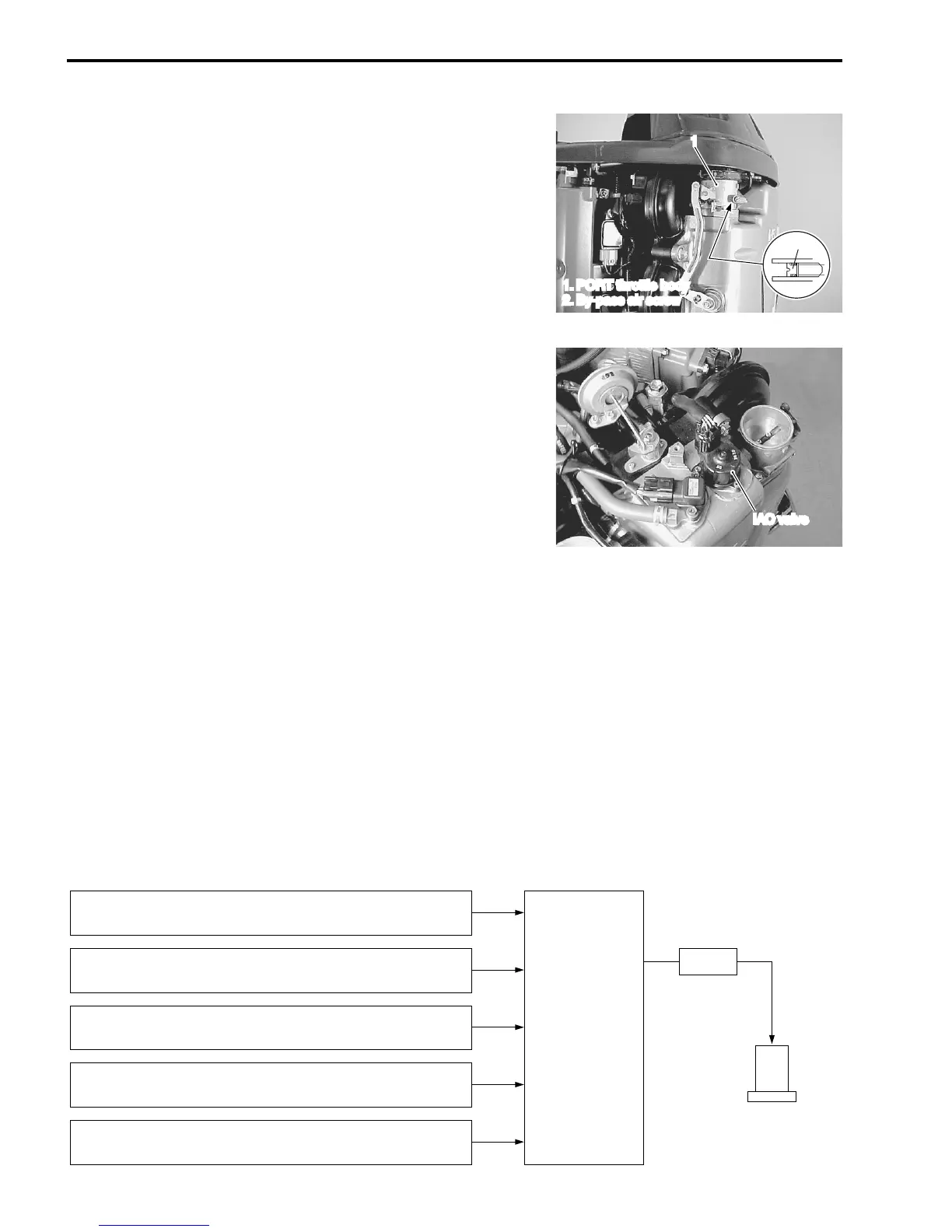
The sensors/switch shown below monitor current engine condition and send signals to the ECM.
Based on these signals, the ECM determines the IAC valve opening necessary to achieve the target engine
revolution and outputs the signal for actuating the stepper motor inside the IAC valve.
The rotor of the stepper motor then turns in an amount equal to the steps of the signal supplied from the
ECM, moving the valve via a screw shaft.
1
2
1. PORT throttle body
2. By-pass air screw
IAC valve
CKP sensor:
Informs ECM of engine speed.
MAP sensor:
Informs ECM of collector (surge tank) pressure.
Throttle position sensor:
Informs ECM of throttle opening angle.
Cylinder temp. sensor:
Informs ECM of cylinder temperature.
Shift position sensor:
Informs ECM of shift position and change.
ECM
Signal
IAC valve

 Loading...