3-34 ENGINE CONTROL SYSTEM
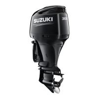
OCV (Oil Control Valve)
Two OCV are used, one installed on each (PORT/STBD) lower
camshaft housing.
RETARD OPERATION
When the duty ratio of the ECM is small, the OCV spool valve is
pushed away from the coil by spring force and engine oil pres-
sure is applied to the retard chamber.
Engine oil remaining in the advance chamber is drained out
through the spool valve.
ADVANCE OPERATION
When the duty ratio of the ECM is large, the spool valve is
towards the coil by magnetic force, compressing the spring and
applying engine oil pressure to the advance chamber side.
Engine oil remaining in the retard chamber side is drained out
through the spool valve.
RETAINING OPERATION
When the duty ratio of the ECM is medium, the OCV coil mag-
netic and return spring forces are equal. This positions the spool
valve between the advance and retard chamber, closing both oil
passages.
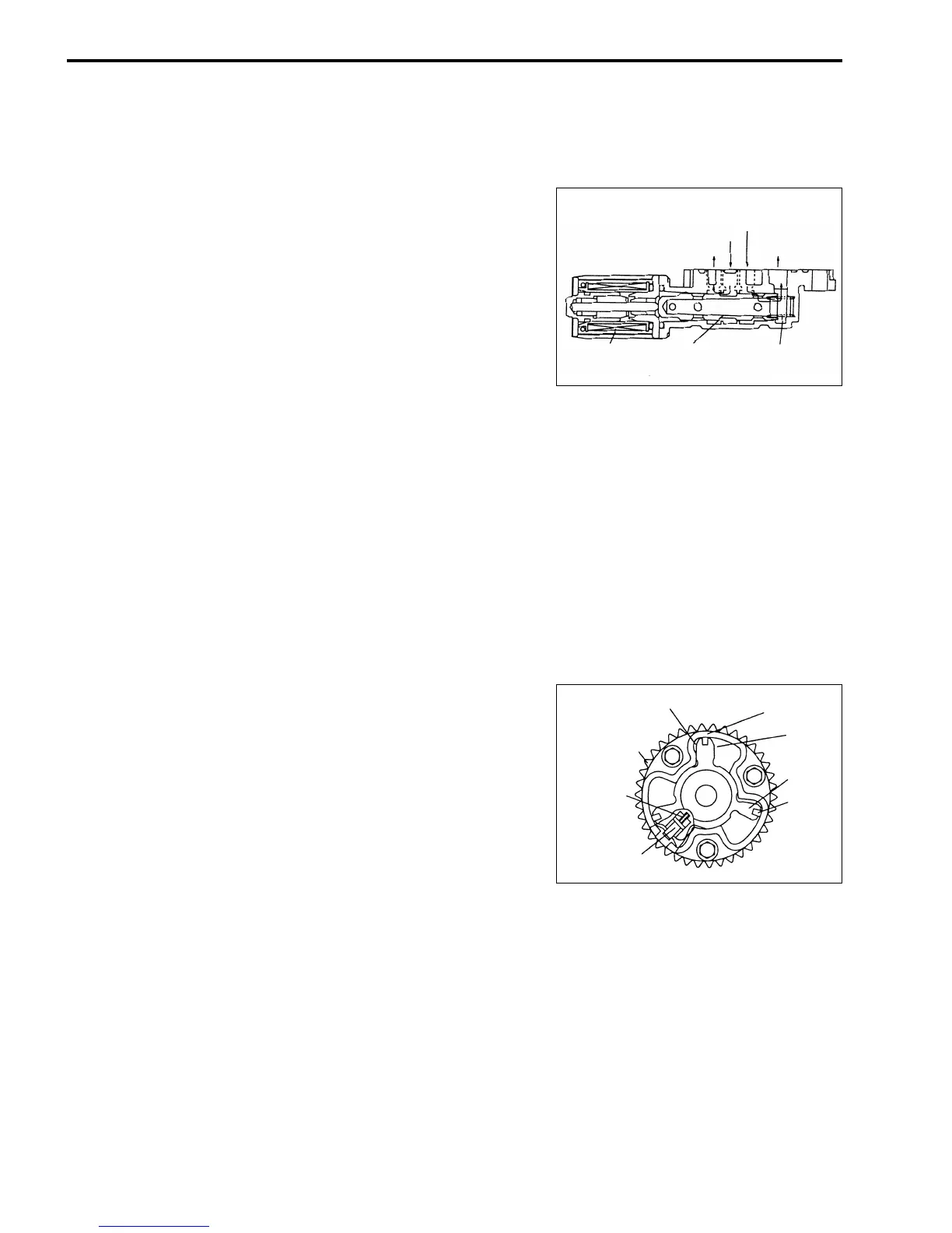
INTAKE CAM TIMING SPROCKET ASSY
Inside the intake cam timing sprocket assembly (VVT actuator),
there are separate advance chamber and retard chamber
formed by partition of the rotor.
The rotor moves inside the housing as engine oil pressure is
applied to the advance or retard chamber.
The intake cam timing sprocket is part of the sprocket housing
assembly. Since the rotor and intake camshaft are bolted
together, when the rotor moves inside the housing, a change of
phase angle takes place in the relative position between the
intake camshaft and intake cam timing sprocket. The rotor has a
spring pressured lock pin which engages with the housing when
spring force is greater than oil pressure, locking the rotor in the
most retarded position. This prevents a change of phase angle
between the intake camshaft and intake cam timing sprocket
when the engine oil pressure is low at engine start.
When the engine is started and the engine oil pressure is
applied to the advance chamber, the lock pin is forced up, com-
pressing the return spring, releasing the rotor and allowing the
VVT actuator to function.
Coil Spool valve
Spring
Engine oil pressure
Retard chamber
Advance chamber
Drain
Retard operation
Advance chamber
Housing
Retard
chamber
Rotor
Seal
Lock pin
Spring
Intake cam
timing sprocket

 Loading...