Manual Transmission/Transaxle: 5B-14
2) Assemble components parts referring to “Gear Shift
Lever Front Case Assembly Components: ”.
3) Set new gear shift arm inner pin (1) and outer pin (2)
facing each gap (“a”, “b”) as shown in figure.
Drive gear shift arm pins by using special tool, till the
length “c” becomes the specified. (The length “c” is
the length of the pin protrusion from gear shift shaft
(4) and select arm (3)).
Special tool
(A): 09925–78210
Gear shift arm pin protrusion “c”: 0.5–1.5 mm
(0.020–0.059 in.)
Gear Shift Lever Front Case Assembly
Inspection
S5JB0A5206033
• Check that gear shift shaft moves smoothly without
abnormal noise. If abnormality is found, replace
defective part.
• Check bushes and boot for damage and deterioration.
If abnormality is found, replace defective part.
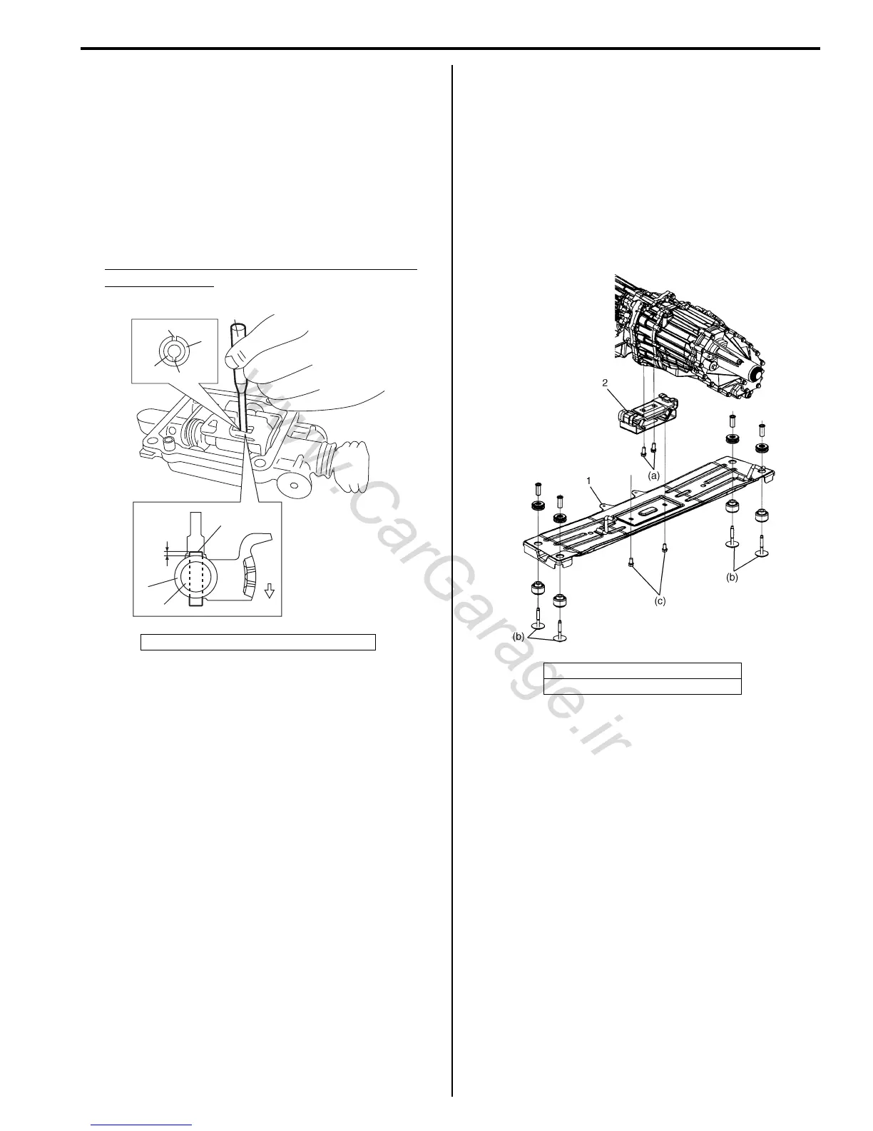
Engine Rear Mounting Replacement
S5JB0A5206010
When replacement of mounting parts are necessary,
torque bolts as specified below.
Tightening torque
Engine rear mounting No.1 bolt (a): 55 N·m (5.5 kgf-
m, 40.0 lb-ft)
Engine rear mounting member bolt (b): 55 N·m (5.5
kgf-m, 40.0 lb-ft)
Engine rear mounting No.2 bolt (c): 55 N·m (5.5 kgf-
m, 40.0 lb-ft)
Manual Transmission Assembly Dismounting
and Remounting
S5JB0A5206011
Dismounting
1) Disconnect negative (–) cable of battery.
2) Remove transmission shift control lever referring to
“Transmission Shift Control Lever Removal and
Installation: ”.
3) Detach engine harness clamps and ground wire
harness from transmission front case.
4) Remove starting motor fastening bolts (2) and
transmission fastening bolts (1).
5. Case side
“a”
“b”
1
2
(A)
“c”
1, 2
3
4
5
I5JB0A520014-01
1. Engine rear mounting member
2. Engine rear mounting
I5JB0A520015-01

 Loading...


