Manual Transmission/Transaxle: 5B-28
Countershaft and Reverse Idle Gear Inspection
S5JB0A5206020
• Using micrometer, check diameter of countershaft (1)
and needle bush (2) as shown. If measured value is
out of specification, replace counter and/or bush.
Countershaft diameter (standard)
• Measure width “a” of low speed gear shift fork and
groove width “b” of low speed gear synchronizer
sleeve and then calculate clearance “c” as follows:
If clearance exceeds limit, replace fork bush (1) and
sleeve.
Clearance “c” between fork and sleeve
Standard: 0.3 – 0.5 mm (0.012 – 0.020 in.)
Limit: 1.0 mm (0.039 in.)
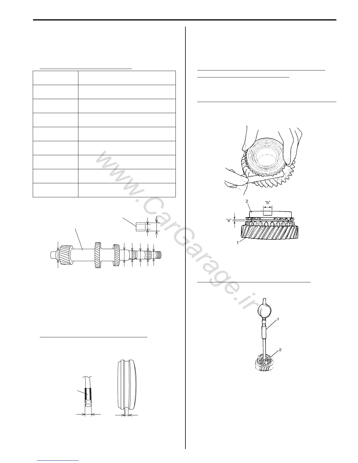
• Check clearance “a” between synchronizer ring (2)
and gear (1), key slot width “b” in synchronizer ring
and each chamfered tooth of gear and synchronizer
ring and replace with new one, if necessary. Also,
check gear tooth.
Clearance “a” between synchronizer ring and
gear (Countershaft) (1st and 2nd)
Standard: 1.0 – 1.4 mm (0.040 – 0.055 in.)
Service limit: 0.5 mm (0.020 in.)
Key slot width “b” (1st and 2nd synchronizer ring)
Standard: 10.0 – 10.2 mm (0.394 – 0.401 in.)
Limit: 10.45 mm (0.411 in.)
• Using cylinder gauge (1), check inside diameter of
countershaft 1st and 2nd gears (2). If measured value
exceeds specification, replace countershaft 5th gear.
Countershaft 1st and 2nd gears diameter
Standard: 40.000 – 40.025 mm (1.5748 – 1.5757 in.)
Measuring
portion
Standard
“a”
25.002 – 25.015 mm
(0.9843 – 0.9848 in.)
“b”
27.987 – 28.000 mm
(1.1019 – 1.1023 in.)
“c”
27.987 – 28.000 mm
(1.1019 – 1.1023 in.)
“d”
30.959 – 30.975 mm
(1.2189 – 1.2194 in.)
“e”
34.975 – 34.991 mm
(1.3770 – 1.3775 in.)
“f”
30.002 – 30.015 mm
(1.1812 – 1.1816 in.)
“g”
28.000 – 28.013 mm
(1.1023 – 1.1028 in.)
“h”
34.975 – 34.991 mm
(1.3770 – 1.3776 in.)
Clearance “c” = “b” – “a”
“c”
“d”
“e”
“f”
“g”
“h”
“b”
“a”
1
2
I5JB0A520078-01
1
“a” “b”
I5JB0A520055-01
I5JB0A520079-01
IYSQ01522122-01

 Loading...


