4-20 DRIVE TRAIN
TOOTH CONTACT
After backlash adjustment and left shim selection are carried
out, the tooth contact must be checked. Pay attention to the fol-
lowing procedures:
• Remove the ring gear.
• Clean and degrease several teeth on the ring gear and pinion
gear, and then apply a coating of machinist’s layout dye or
paste to several teeth of the pinion gear.
• Install the ring gear with the shims in place.
• Install the gear case cover, and then tighten the bolts to the
specified torque in a crisscross pattern. (4-14)
Gear case cover bolt: 25 N·m (2.5 kgf-m, 18.0 lb-ft)
NOTE:
At this time, it is not necessary to install the gear case cover’s O-
ring.
• Rotate the gear several turns in each direction. This will pro-
vide a contact pattern on the coated teeth of the gear.
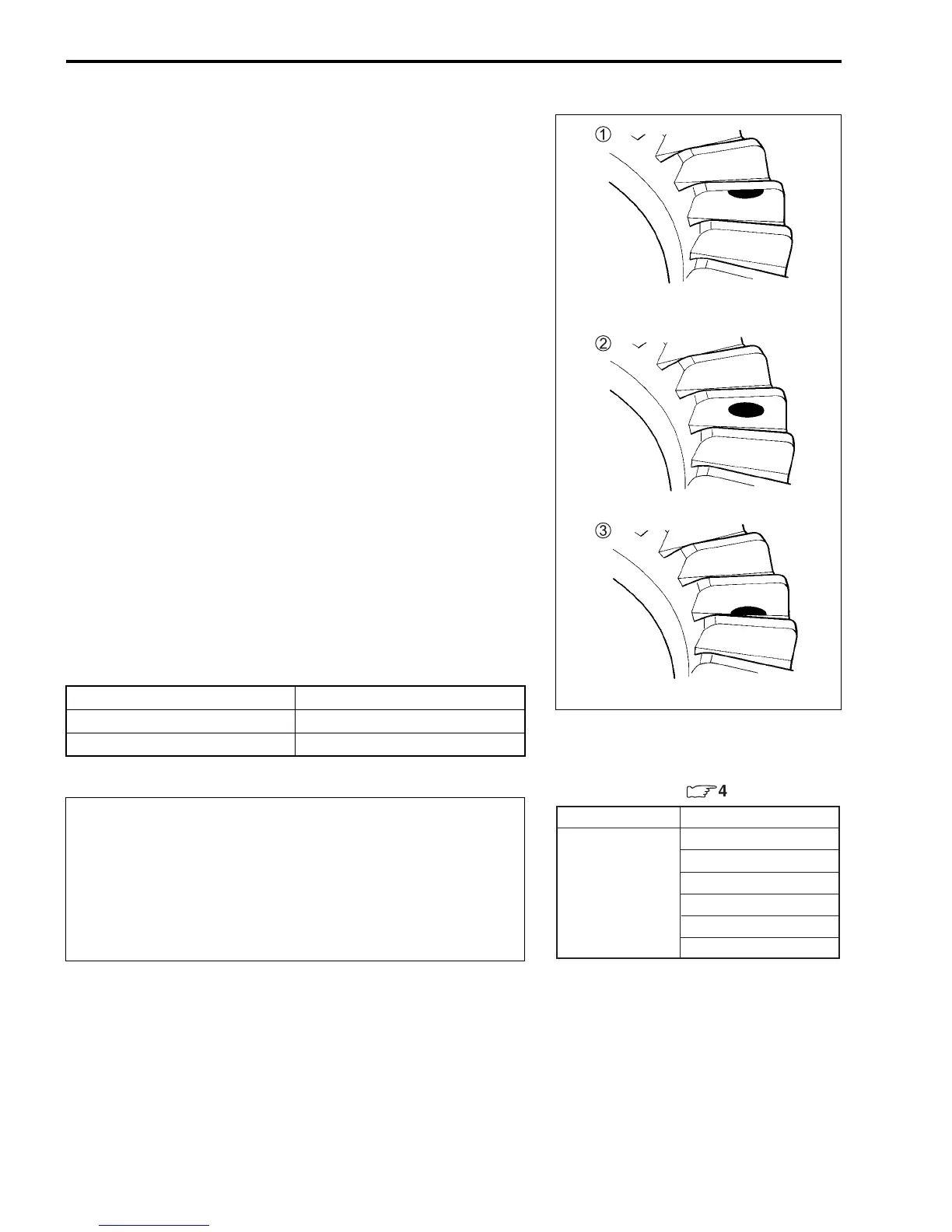
• Remove the ring gear and compare the coated teeth to the
examples shown in 1, 2 and 3.
• If tooth contact is found to be correct (example 2), go to the
FINAL ASSEMBLY sub-section on p.4-13 and 4-14 to com-
plete installation.
• If tooth contact is found to be incorrect (examples 1 and 3),
the shim between the pinion gear bearing and gear case must
be changed and the tooth contact re-checked until correct.
Tooth contact Shim adjustment
Contact at tooth top 1 Decrease shim thickness
Contact at tooth root 3 Increase shim thickness
Make sure to check the backlash and shim thickness
after the tooth contact has been adjusted, since it may
have changed. Adjust the tooth contact and backlash
until they are both within specification. If the correct
tooth contact cannot be maintained when adjusting
the backlash, replace the pinion gear and ring gear as
a set.
(Contact at tooth top)
(Contact at tooth root)
Correct
Incorrect
Incorrect
Part No.
Shim thickness
For pinion gear (
:
4-21)
1.38 mm (0.0543 in)
1.44 mm (0.0567 in)
1.50 mm (0.0591 in)
1.56 mm (0.0614 in)
1.62 mm (0.0638 in)
1.68 mm (0.0661 in)
27407-05810
(Shim set: 6 pcs)
 Loading...


