Annex9—1
Speedcontrolforrotorandassemblyofdividedrotor
Annex9.
9.1Speedcontrol
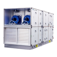
Thecabinetwiththespeedcontrolsystemfo rtherotorisinstalledbehindtheinspectiondoorintherotor
section.
Thecabinetcontainsthespeedcontrollerwithallcomponents,terminalblocks,LEDdisplayingthe
operationmode,thedualpositionDIPswitchwith4slidingleversforprogrammingtherotormotor
signal
andabuttonfortheactivationofthetestmode.
Throughthedifferentcombinationsofthe4slidingleversofthisdualpositionDIPswitch,thecorrectsignal
isavailableforthe3differentmotorsusedforthe14sizesofairhandlingunits.Theslidingleversareset
and
thefunctionischeckedatthefactory.Thepositionsoftheleversappearfromthetablesbelow.
9.1.1Selectionofcorrectsignalviathe4DIPswitchlevers
The4DIPswitchlevers
Position Function Code
Up Active=ON 1
Down Deactivated=OFF 0
Thefactorysetsthepositionsofthe4DIPswitchleversforthemaximumof10revolutionsperminute
forstandardtemperatureexchangersandforhygroscopicexchangers.ThepositionofeachDIPswitch
leverisshownbelow.
DV Diameter of
pulley
DIPswitchposition Motor
10 50
0000
90TYD‐S214‐M2.8Nm
15 50
20 50
25 65
30 65
40 65 1000
50 71
0100
120TYD‐S214‐M5.5Nm
60 80
80 85
100 95
120 106
150 112
190 132
0010 120TYD‐S214‐L7.5Nm
240 140
 Loading...