Annex10—1
Internalcontrollerinthecoolingcompressorunits
Annex10.
10.1DVU–section(coolingunit)
Theairhandlingunitsection–DVU–isaseparatesectionintheairhandlingunit,andthesectioncontains
acompletestand‐alonecoolingcompressorsystem.Thesystemhasbeenstarted,adjustedandoptimized
beforethedelivery.Therefrigerantisevaporateddirectlyinthecoolingcoilandthecooling
capacityis
regulatedautomaticallyandsteplesslybetween10and100%.ThesystemisdeliveredwiththeHFC
refrigerantR‐407Cinthecircuit.InternallyinthesectionaDVU‐internalcontroller‐LMC251‐andcomplete
controlsystemtakecareofallsafetyfunctionsaswellasthefrequencyconverterregulated
compressor
thatcreatesexactlythecoolingcapacityorderedbythemainairhandlingunitcontrollerviathevery
common0‐10VDCsignal.Whenthedemandforcoolingoccursintheroom,themainairhandlingunit
controllersendsastartsignalandasignalexceeding0volttothecooling
compressorsystem.Whenthe
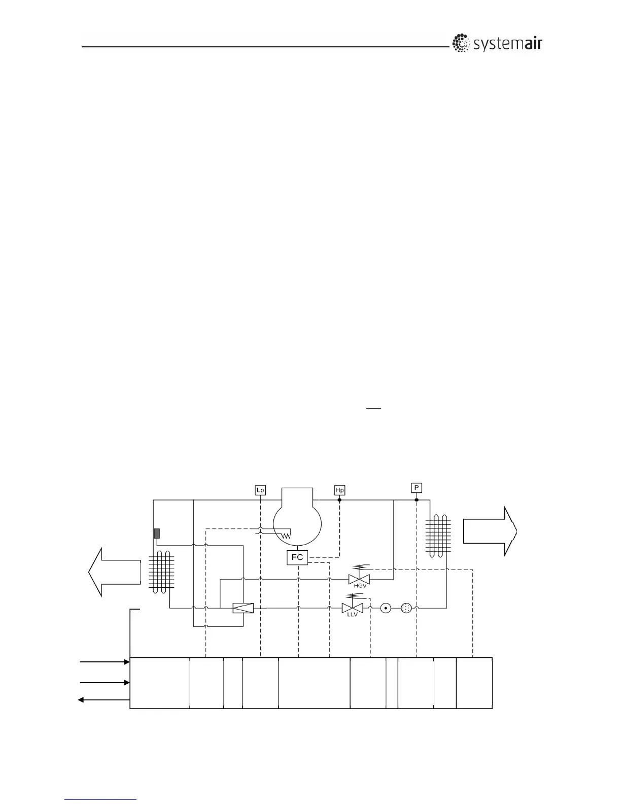
signalexceeds1.5voltthecoolingcompressorstarts.Afterstart‐upthecapacityisregulatedbetween10
and35%bythehotgasvalve(HGVintheillustrationbelow)inon/offinsequenceswiththecooling
compressoratthelowestnumberofrevolutions.Whenmorethan
35%ofthecoolingcapacityis
demanded(signalexceedsmorethan3,5volt)thehotgasvalvecloses,thecoolingcapacityisregulatedby
thefrequencyconverter(FCintheillustrationbelow)tothestrictlynecessaryrevolutionsofthe
compressor.Bydecliningdemandwiththecompressoratthelowestrevolutions,the
hotgasvalveis
regulatedon/offinsequences,whenthedemandislessthan34%.Thecoolingcompressorstopswhenthe
demandislessthan10%.Toavoidthatthecompressorstopsbecausethehighpressureswitch(Hpinthe
illustrationbelow)cutsoff,anautomaticcapacityreductionsystem
isinstalled.Thecapacityreduction
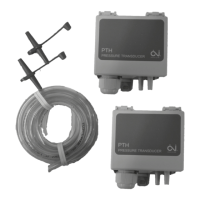
systemconsists ofapressuretransducer(Pintheillustrationbelow)installedinthehighpressurepipe
betweenthecompressorandthecondenserandsoftwareintheDVU‐internalcontrollerthatreducesthe
revolutionsofthecompressortoavoidthatthepressureafterthecompressordevelops
tothecut‐off
pressureofthehighpressureswitch–thesystemdoesnotstop;itwillalwaysremaincoolingtosome
extent.Airvolumecapacitiesforsupplyfanandforexhaustfanarenotregulatedbythebuilt‐incontroller–
LMC251 ‐forthecoolingsystem,butbythemainairhandlingunitcontroller.Thetechnicianfroma
certifiedinstallerofcoolingunitsmustagreewiththeinstalleroftheventilationsystemandthemainair
handlingunitcontrollerthattheairvolumesforthesystemarenotgoingtoexceedthe
maximumortobe
lowerthantherecommendedminimummentionedbelowinsection3.2.5.18inthismanual
3*400
VAC
Analogin
Digitalin
Alarmout
RS485
COM
Extract
Relay
out
Digital‐
in
Relay‐
out
Analog‐
in
Relay
out
 Loading...