10
|
Description GB
• Voltage/current/enclosure class/weight/impeller diameter = see name plate
• Sound pressure [dB(A)] = see data sheet
Note:
Further technical data can be found on the data sheet of your fan.
5.3 Description MUB-CAV/VAV
The fans are driven by EC motors. All motors and the controller are suitable for 50/60 Hz. All models have one poten-
tial- free terminal for error messages. The input voltage for single phase units can vary between 200 and 277 V for
three phase units between 380 and 480 V. Please observe that the input voltage of the controller can vary between
195 and 253 V. The MUB—CAV/VAV with the integrated controller offers you the possibility for a constant airflow (fac-
tory setting) or a constant pressure ventilation or just to display data.
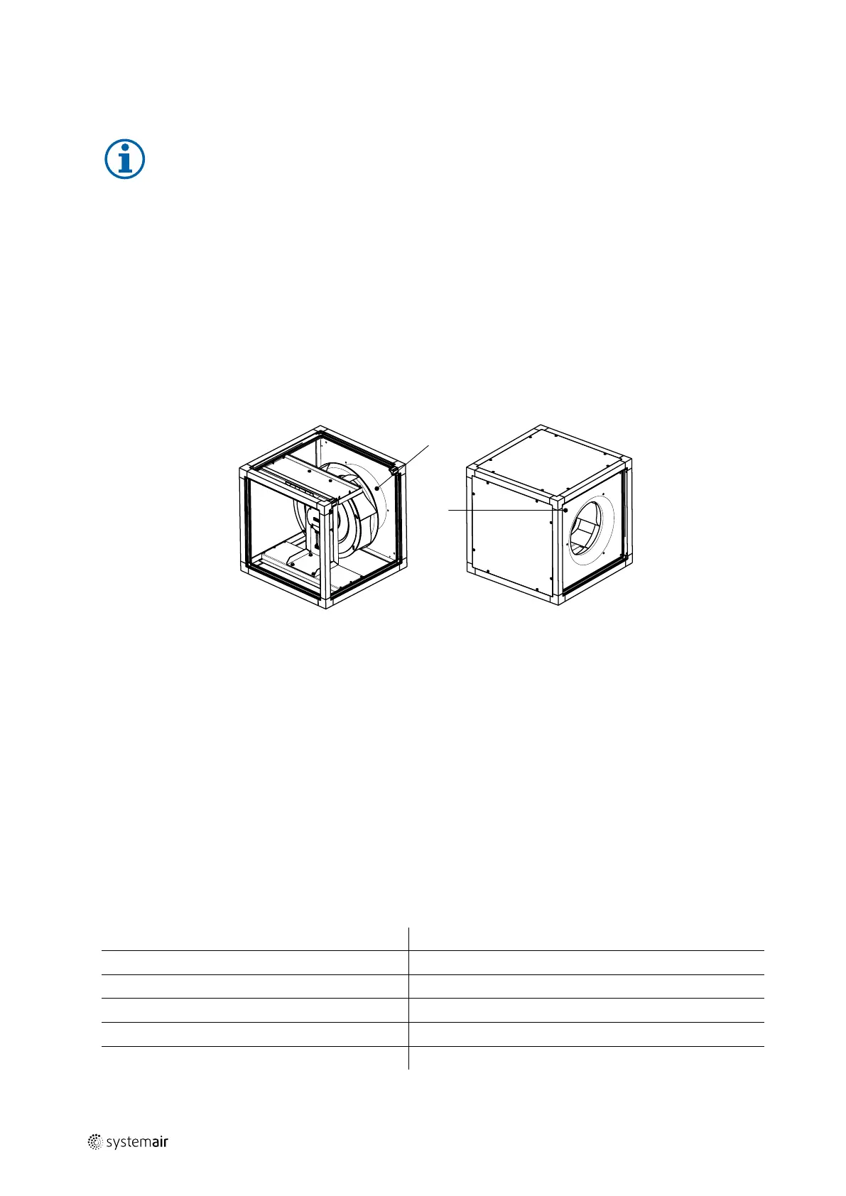
5.3.1 Constant air volume function (CAV)
If the air volume (factory setting) is to be kept constant, the differential pressure in front of the inlet cone and in the in-
let cone must also be kept constant.
1
measuring point — inlet cone
2
measuring point — in front of the inlet cone
5.3.2 Constant pressure - variable air volume function (VAV)
If the pressure in the duct system is to be kept constant, the differential pressure between atmosphere and duct system
must also be kept constant. For this operation mode, the position of the measuring tubes must be changed using the
„constant pressure kit“. This kit and its manual are included in the MUB—CAV/VAV.
5.3.3 Sensor control module for differential pressure and volume PCA1000/6000D2
5.3.3.1 General
The factory setting of the controller is CAV (constant air volume). The measured value is compared with the setpoint
value. The controller adjusts the 0-10 V controlled output for the EC motor to keep the air volume constant. The specific
characteristics of the inlet cone size are considered in the k-factor. Table 4 K-factor, page 10. For more detailed infor-
mation of the controller module (PCA1000/6000D2), see operating manual of the controller.
Table 4 K-factor
Designation
K-Factor
Designation
K-Factor
MUB-CAV/VAV 025 315EC
100
MUB-CAV/VAV 042 500EC
266
MUB-CAV/VAV 025 355EC
143
MUB-CAV/VAV 062 560EC
418
MUB-CAV/VAV 042 400EC
172
MUB-CAV/VAV 062 630EC
500
MUB-CAV/VAV 042 450EC
238
MUB-CAV/VAV 100 630EC
456
MUB-CAV/VAV 042 450EC-K
235
MUB-CAV/VAV 100 710EC
550
| 001
 Loading...