TB9100 Reciter Service Manual Reciter Circuit Descriptions 19
© Tait Electronics Limited January 2006
2 Reciter Circuit Descriptions
This chapter describes the circuitry used in VHF and UHF reciters.
Much of this circuitry is common to both frequency bands, and is therefore
covered by a single description in this chapter. Where the circuitry differs
between VHF and UHF, separate descriptions are provided for each
frequency band. In some cases the descriptions refer to specific VHF or
UHF bands or sub-bands, and these are identified with the letters listed in
the following table.
The reciter comprises three PCBs: an RF, a digital, and a network PCB.
These PCBs are mounted on a central chassis/heatsink. Figure 2.1 on
page 20 shows the configuration of the main circuit blocks, and the main
inputs and outputs for power, RF and control signals. The locations of the
main circuit blocks on the PCBs are shown in Figure 5.1 on page 36.
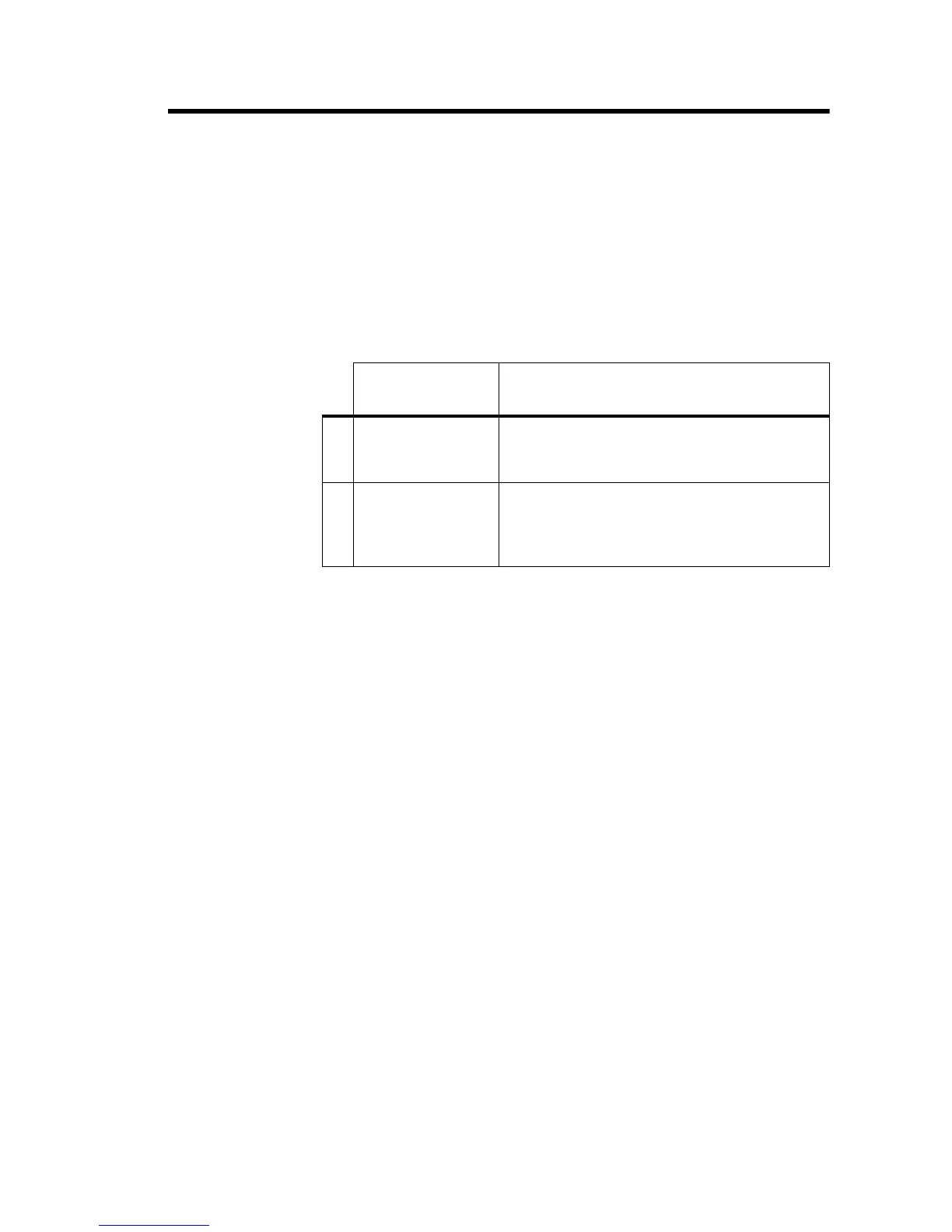
Table 2.1 TB9100 frequency bands
Frequency
Identification Frequency Band and Sub-band
VHF
B band B1 = 136MHz to 174MHz
B2 = 136MHz to 156MHz
B3 = 148MHz to 174MHz
UHF
H band H0 = 400MHz to 520MHz
H1 = 400MHz to 440MHz
H2 = 440MHz to 480MHz
H3 = 470MHz to 520MHz

 Loading...


