TB9100 Reciter Service Manual RF Circuitry 91
© Tait Electronics Limited January 2006
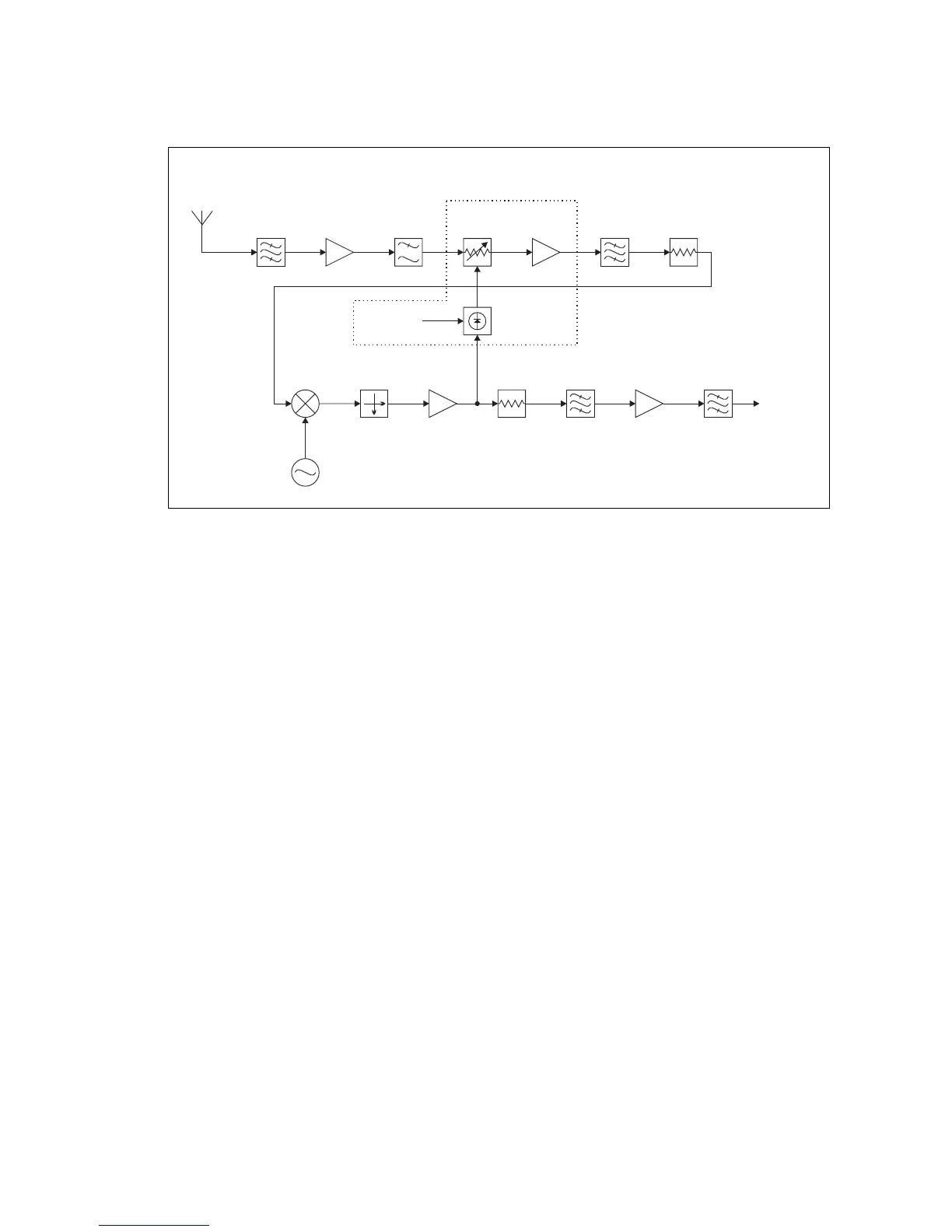
6.2 Receiver RF Circuitry - UHF Reciter
6.2.1 Front End
H Band Reciter The incoming signal from the BNC connector is fed through a triplet helical
filter, followed by a simple low pass network which attenuates harmonics
and spurious responses from the preceding filter. The signal is then amplified
and passed through a low pass filter which provides immunity to interference
from higher frequency out-of-band signals. Automatic gain control (AGC)
is provided at this point by a PIN diode attenuator. The signal is now
amplified again in a second RF amplifier, and is then fed through a band pass
filter and attenuator pad to the mixer.
6.2.2 Mixer
The RF signal from the front end is converted down to the 70.1MHz IF by
a high level (+17dBm local oscillator) mixer. The voltage controlled
oscillator (VCO) generates a level of 20dBM which is fed to the mixer
through an attenuator pad. A diplexer terminates the IF port of the mixer in
50Ω, thus ensuring a good match for all mixing products, as well as
enhancing the linearity. The post-mixer buffer amplifier compensates for
the insertion loss of the crystal filter, and any excess gain is reduced by the
following attenuator pad.
Figure 6.3 Reciter UHF Receiver RF Circuitry Block Diagram
Attenuator
Pad
Band Pass
Filter 1
Band Pass
Filter 2
RF
Amplifier 1
RF
Amplifier 2
Low Pass
Filter
PIN
Attenuator
AGC not fitted to
K band reciters
Attenuator
Pad
AGC Control AGC Detector
Mixer
Local Oscillator
Diplexer
Post-mixer
Buffer
Crystal
Filter
IF
Amplifier
Anti-alias
Filter
IF Output
RF In
H Band

 Loading...


