Page 18 • MN03010 ║ Issue/Rev. 0.4 (6/17)
Model 210 Valve (I / O / S) Manual Service and Maintenance
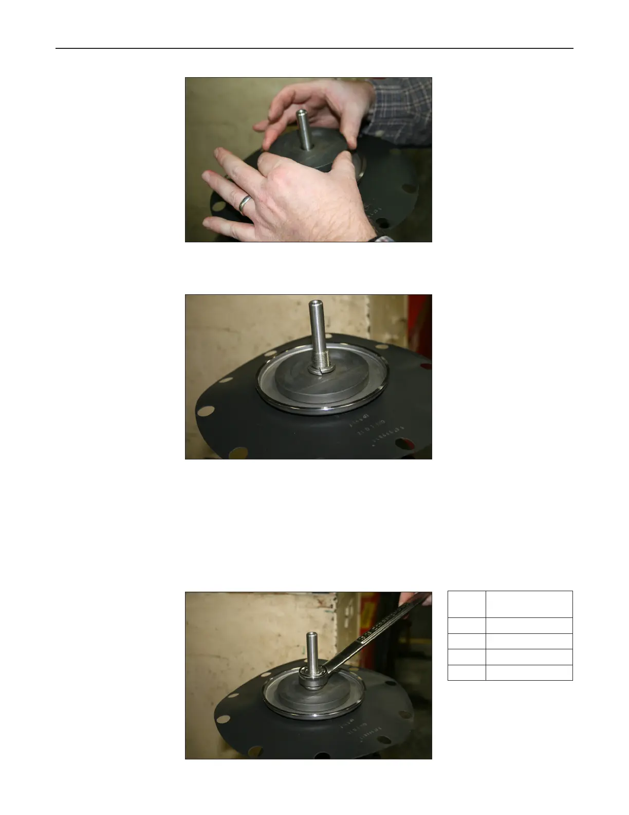
Figure 24 – Back-up Plate Installation
Install the lock washer on the stem.
Figure 25 – Lock Washer
Apply LOCTITE
®
Nickel Anti-Seize 77164 on the threads of the stem before placing
the stem nut.
Secure the stem nut to the stem using a socket or open ended wrench. Tighten until
the lock washer engages against the surface of the back-up plate and the stem nut.
Then, use a torque wrench and apply the torque value as indicated in the table below
for the specific valve size:
Figure 26 – Engaged Lock Washer
Valve
size
Torque value
of stem nut
2 Inch 14-17 ft-lbs
3 Inch 25-30 ft-lbs
4 Inch 60-65 ft-lbs
6 Inch 130-140 ft-lbs
Note: The 2 inch valve does not
use a lock washer. Instead, it uses
a counter nut. Fasten the rst nut
with the torque indicated in the
table (14-1') ft-lbs and then add
the counter nut and fasten with
same torque.
 Loading...