Issue/Rev. 0.4 (6/17) ║ MN03010 • Page 23
Model 210 Valve (I / O / S) Manual Service and Maintenance
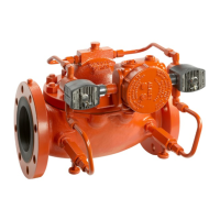
If the valve has been removed from the piping, the valve can be rested on the inlet or
outlet flange to allow proper leverage.
Figure 35 – Torque Cover Nuts
Install the junction box and junction box bracket and install solenoids. Note the
position of the longer studs. These are to be used for the junction box installation.
If solenoid fittings were removed or replaced, lightly dress fitting threads with Loctite
565 thread sealant.
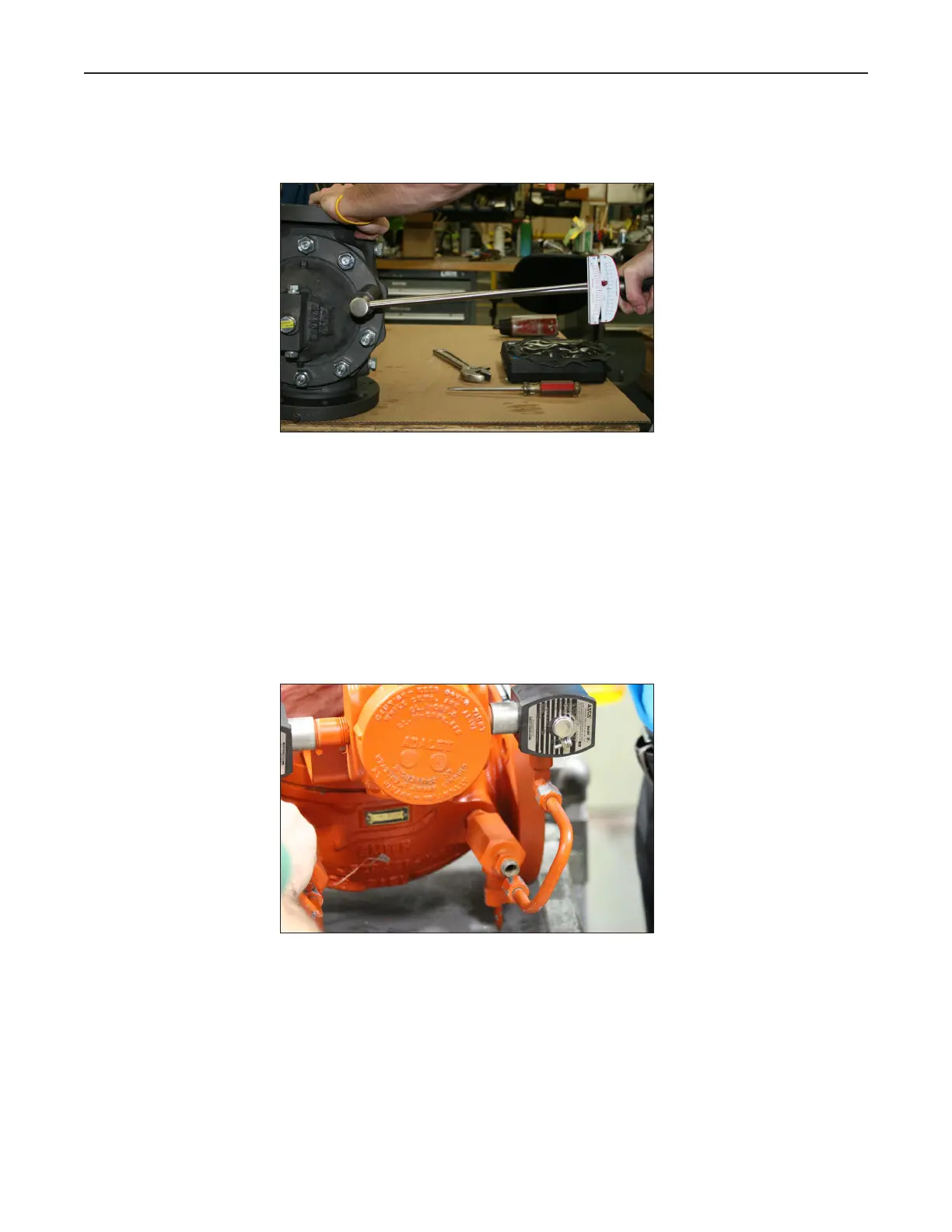
Reinstall the valve tubing. The tubing can be reused if in good condition. Install tubing
by loosely securing the tubing fitting to the solenoid fitting. This will allow the tubing
to be somewhat flexible and will make installation simpler. Once all tubing is in place,
secure tubing with an open ended wrench. Ensure not to over tighten as this could
crush the tubing and create a leak path.
Figure 36 – Tubing Installation
 Loading...