Page 22 • MN03010 ║ Issue/Rev. 0.4 (6/17)
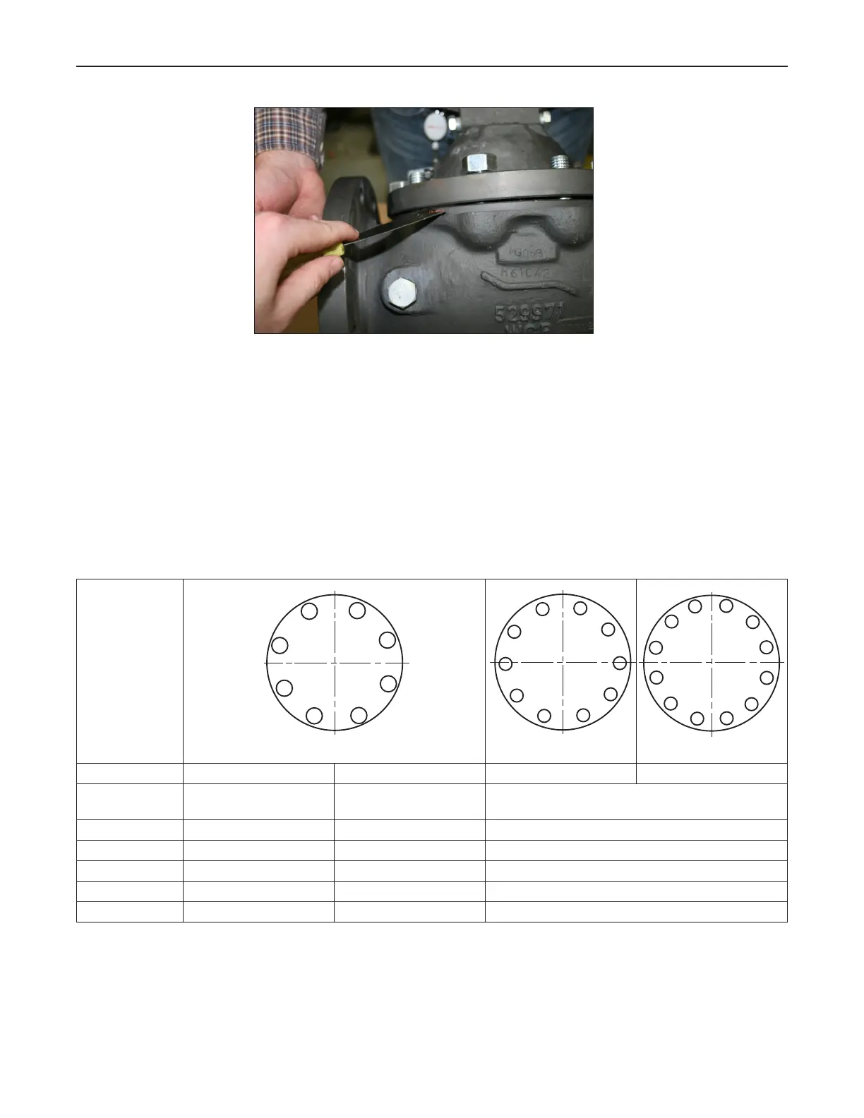
Figure 34 – Cover Installation
Continue tightening the cover nuts by hand until they require a wrench and the rabbit
of the cover completely covers the valve body. Install the remaining nuts by hand.
As the nuts are being tightened, check for gap uniformity of the valve body and
cover. Once the nuts are snug, using a manual torque wrench tighten the nuts per
the sequence as shown in the table and diagrams below (Table 1).
Model 210 Valve (I / O / S) Manual Service and Maintenance
Valve Size: 2 Inch (8 bolt) 3 Inch (8 bolt) 4 Inch (10 bolt) 6 Inch (12 bolt)
Nominal Bolt
Size:
5/16-18 7/16-14 5/8-11
Round 1: Hand tighten to snug Hand tighten to snug Hand tighten to snug
Round 2: Tighten to 10 ft-lbs Tighten to 25 ft-lbs Tighten to 35 ft-lbs
Round 3: Tighten to 20 ft-lbs Tighten to 45 ft-lbs Tighten to 90 ft-lbs
Round 4: Tighten to 20 ft-lbs Tighten to 45 ft-lbs Tighten to 150 ft-lbs
Round 5: N/A N/A Tighten to 150 ft-lbs
Table 1 – Cover Nut Torque Valves and Sequence
5
1
5
3
7
2
6
4
8
10 bolt 12 bolt
8
2
7
4
9
6
1
10
5
3
1
6
2
7
9
3
8
4
5
10
11
12
8 bolt
5
1
5
3
7
2
6
4
8
10 bolt 12 bolt
8
2
7
4
9
6
1
10
5
3
8 bolt
5
1
5
3
7
2
6
4
8
10 bolt 12 bolt
8
2
7
4
9
6
1
10
5
3
1
6
2
7
9
3
8
4
5
10
11
12
 Loading...