Displaying Signals
Triggering on Complex or Non-Repetitive Signals
Some signals are too complex or irregular to provide a usable trigger of
there own. Circuits that carry digital information are a good example. Often,
however, a signal from another part of the circuit, such as a more widely
spaced clocking signal, will provide a meaningful trigger event. You can
even view the trigger signal at the same time as the other signal with a
two-channel display:
Step
1:
Connect one signal to Channel
1
and the trigger signal to
Channel
2.
Move the
CHI BOTH CH2
switch to
CH 2.
Step 2:
Set the trigger mode to
NORM
and the
A
&
B SOURCE
to
CH 2.
Step 3:
Adjust the
A TRIGGER LEVEL
to trigger on the signal.
Step
4:
Set the oscilloscope in
STORE.
Step
5:
Move the
CHI BOTH CH2
switch to
BOTH.
Step 6:
Move the
ADD ALT CHOP
switch to
ALT
or
CHOP.
(In general,
it is better to use
CHOP
when the
SECIDIV
control is set in the millisec-
ond (ms) range, and
ALT
when the
SECIDIV
is in the microsecond (ps)
range.)
Step
7:
Position both signals on screen and adjust the vertical and
horizontal scales.
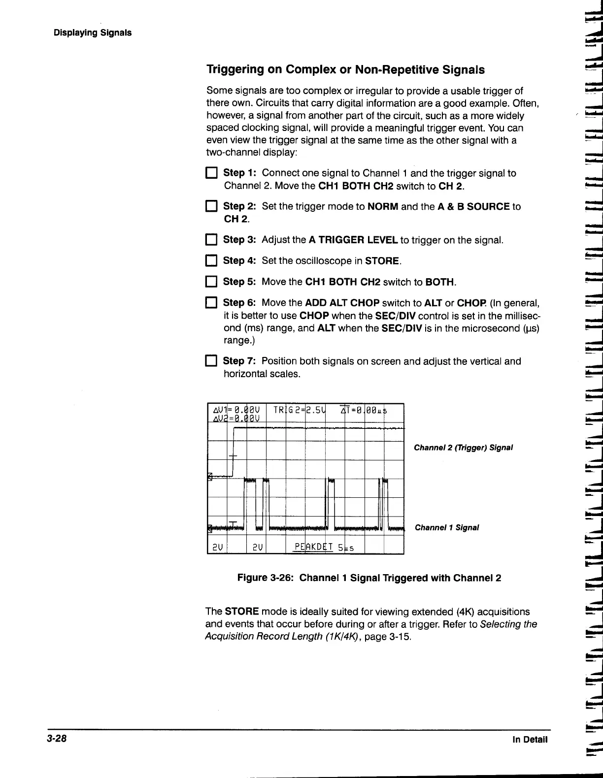
Channel
2
(Trigger) Signal
Channel
7
Signal
Figure 3-26: Channel 1 Signal Triggered with Channel 2
The
STORE
mode is ideally suited for viewing extended
(4K)
acquisitions
and events that occur before during or after a trigger. Refer to Selecting the
Acquisition Record Length
(1
K/4K),
page
3-1
5.
.--
-
3-28
In Detail
1

 Loading...


