5-7
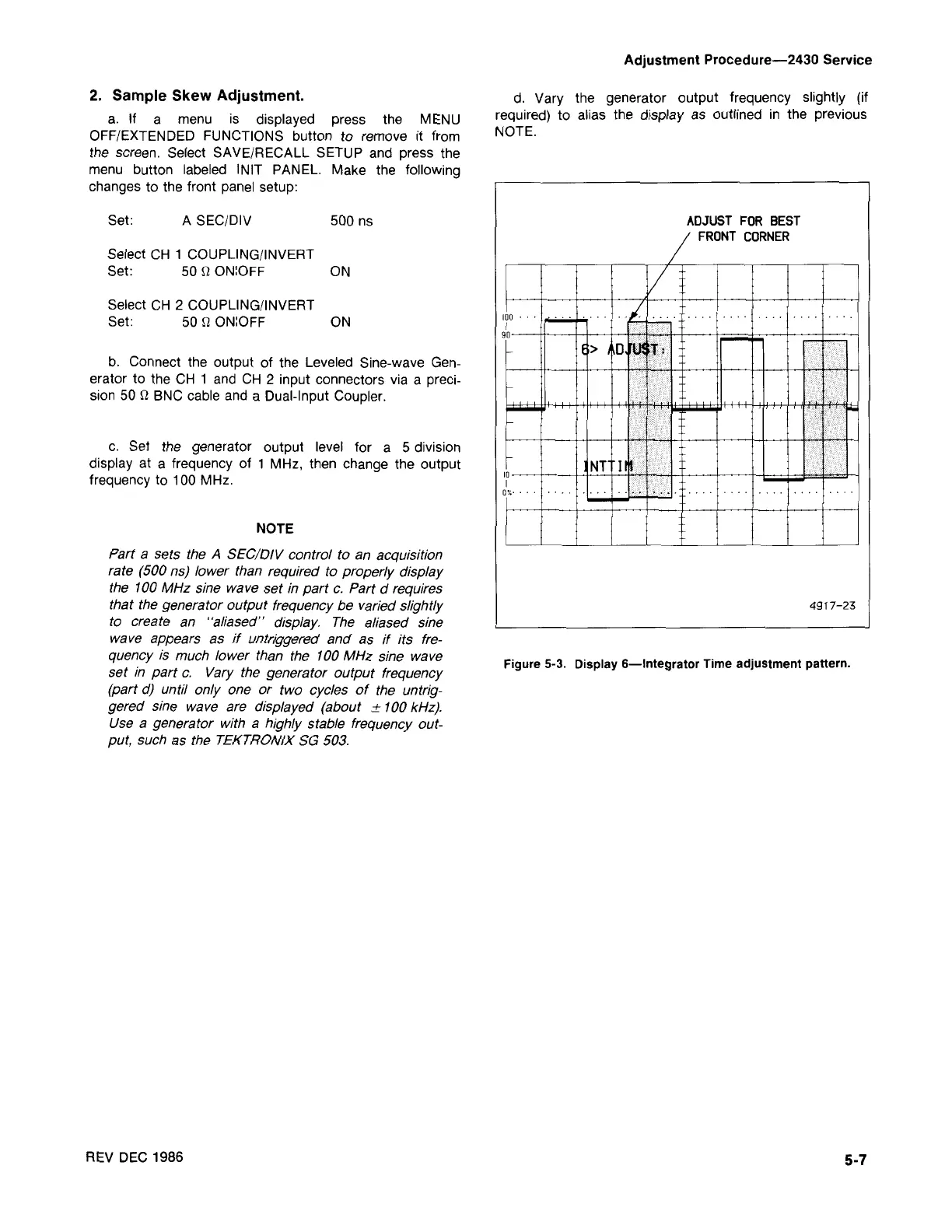
Figure 5·3. Display 6-lntegrator Time adjustment pattern.
49 17-23
ADJUST FOR BEST
FRONT CORNER
d. Vary the generator output frequency slightly (if
required) to alias the display as outlined in the previous
NOTE.
Adjustment Procedure-2430 Service
REV DEC 1986
Part a sets the A SEC/OIV control to an acquisition
rate (500 ns) lower than required to properly display
the 100MHz sine wave set in part c. Part d requires
that the generator output frequency be varied slightly
to create an "eliesed'' display. The aliased sine
wave appears as if untriggered and as if its fre-
quency is much lower than the 100MHz sine wave
set in part c. Vary the generator output frequency
(part d) until only one or two cycles of the untrig-
gered sine wave are displayed (about
±
100kHz).
Use a generator with a highly stable frequency out-
put, such as the TEKTRONIX SG 503.
NOTE
c. Set the generator output level for a 5 division
display at a frequency of 1 MHz, then change the output
frequency to 100 MHz.
b. Connect the output of the Leveled Sine-wave Gen-
erator to the CH 1 and CH 2 input connectors via a preci-
sion 50 n BNC cable and a Dual-Input Coupler.
Select CH 2 COUPLING/INVERT
Set: 50
n
ON:OFF ON
Select CH 1 COUPLING/INVERT
Set: 50
n
ON:OFF ON
500 nsA SEC/DIV
Set:
2. Sample Skew Adjustment.
a. If a menu is displayed press the MENU
OFF/EXTENDED FUNCTIONS button to remove it from
the screen. Select SAVE/RECALL SETUP and press the
menu button labeled INIT PANEL. Make the following
changes to the front panel setup:

 Loading...


