Specification—2445 Operators
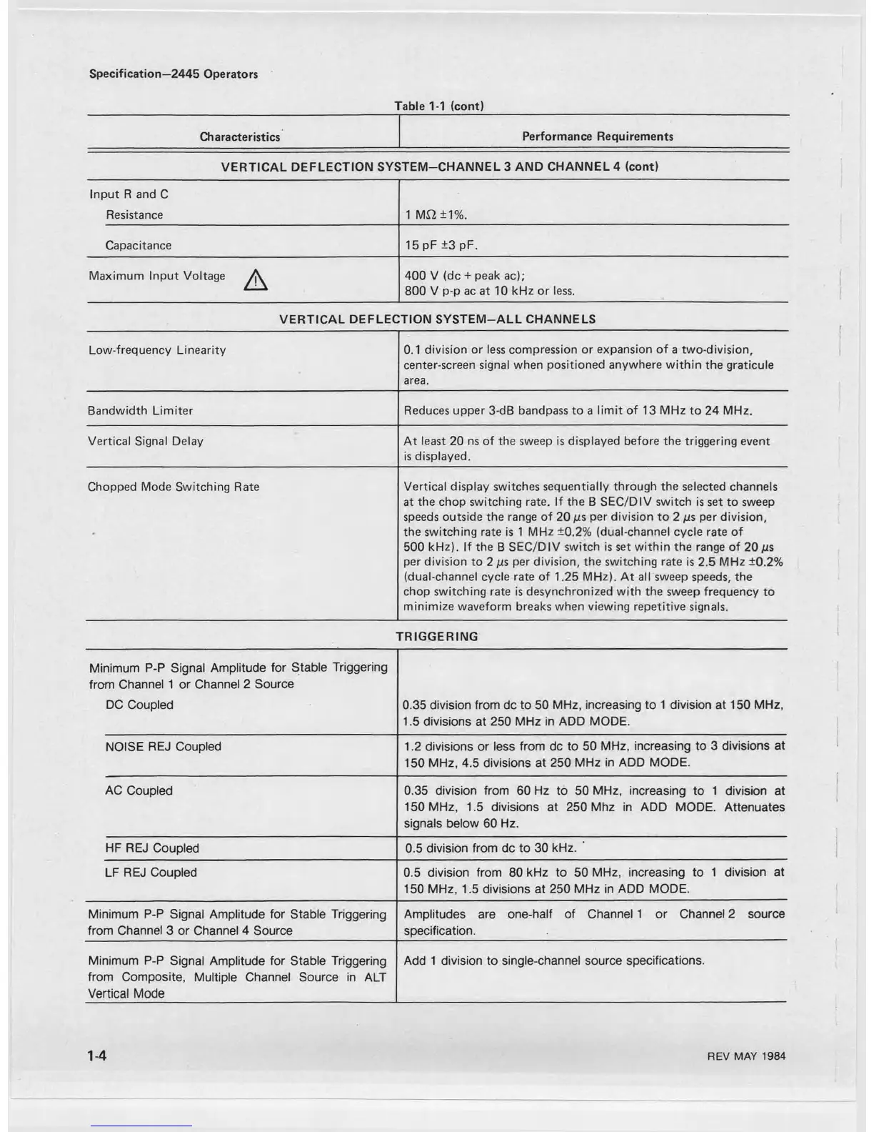
Table 1-1 (cont)
Characteristics
Performance Requirements
VERTICAL DEFLECTION SYSTEM-CHANNEL 3 AND CHANNEL 4 (cont)
Input R and C
Resistance
1 M£2±1%.
Capacitance
15 pF ±3 pF.
Maximum Input Voltage ^ 400 V (dc + peak ac);
800 V p-p ac at 10 kHz or less.
VERTICAL DEFLECTION SYSTEM-ALL CHANNELS
1
Low-frequency Linearity
0.1 division or less compression or expansion of a two-division,
center-screen signal when positioned anywhere within the graticule
area.
Bandwidth Limiter Reduces upper 3-dB bandpass to a limit of 13 MHz to 24 MHz.
Vertical Signal Delay
At least 20 ns of the sweep is displayed before the triggering event
is displayed.
Chopped Mode Switching Rate Vertical display switches sequentially through the selected channels
at the chop switching rate. If the B SEC/DIV switch is set to sweep
speeds outside the range of 20 ps per division to 2 ps per division,
the switching rate is 1 MHz ±0.2% (dual-channel cycle rate of
500 kHz). If the B SEC/DIV switch is set within the range of 20
/jls
per division to 2 ps per division, the switching rate is 2.5 MHz ±0.2%
(dual-channel cycle rate of 1.25 MHz). At all sweep speeds, the
chop switching rate is desynchronized with the sweep frequency to
minimize waveform breaks when viewing repetitive signals.
TRIGGERING
Minimum P-P Signal Amplitude for Stable Triggering
from Channel 1 or Channel 2 Source
DC Coupled
0.35 division from dc to 50 MHz, increasing to 1 division at 150 MHz,
1.5 divisions at 250 MHz in ADD MODE.
NOISE REJ Coupled
1.2 divisions or less from dc to 50 MHz, increasing to 3 divisions at
150 MHz, 4.5 divisions at 250 MHz in ADD MODE.
AC Coupled 0.35 division from 60 Hz to 50 MHz, increasing to 1 division at
150 MHz, 1.5 divisions at 250 Mhz in ADD MODE. Attenuates
signals below 60 Hz.
HF REJ Coupled
0.5 division from dc to 30 kHz. '
LF REJ Coupled 0.5 division from 80 kHz to 50 MHz, increasing to 1 division at
150 MHz, 1.5 divisions at 250 MHz in ADD MODE.
Minimum P-P Signal Amplitude for Stable Triggering
from Channel 3 or Channel 4 Source
Amplitudes are one-half of Channel 1 or Channel 2 source
specification.
Minimum P-P Signal Amplitude for Stable Triggering
from Composite, Multiple Channel Source in ALT
Vertical Mode
Add 1 division to single-channel source specifications.
1-4
REV MAY 1984

 Loading...


