Specification-2445 Operators
Table 1-1 (cont)
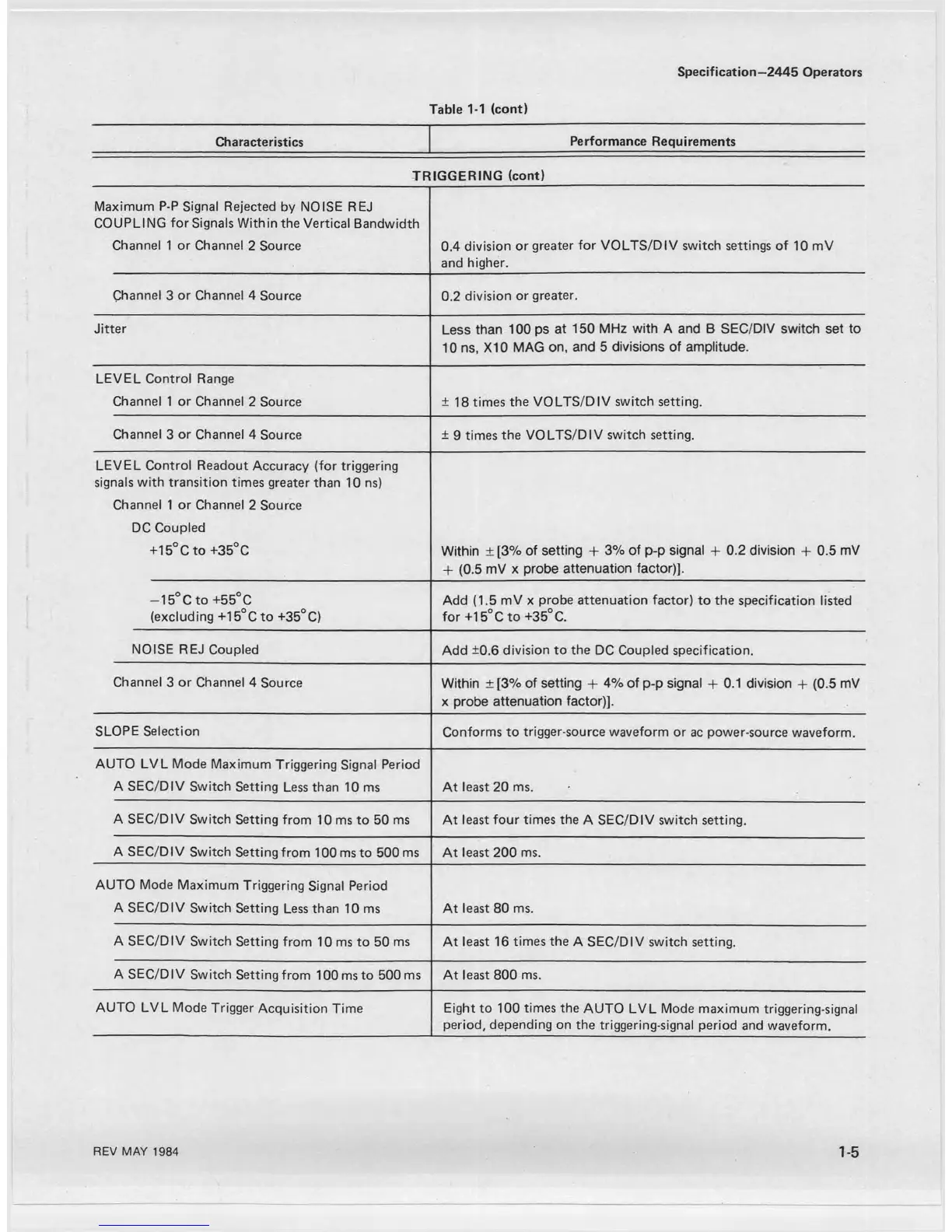
Characteristics
Performance Requirements
TRIGGERING (cont)
Maximum P-P Signal Rejected by NOISE REJ
COUPLING for Signals Within the Vertical Bandwidth
Channel 1 or Channel 2 Source 0.4 division or greater for VOLTS/DIV switch settings of 10 mV
and higher.
Channel 3 or Channel 4 Source 0.2 division or greater.
Jitter
Less than 100 ps at 150 MHz with A and B SEC/DIV switch set to
10 ns, X I0 MAG on, and 5 divisions of amplitude.
LEVEL Control Range
Channel 1 or Channel 2 Source ± 18 times the VOLTS/DIV switch setting.
Channel 3 or Channel 4 Source
± 9 times the VOLTS/DIV switch setting.
LEVEL Control Readout Accuracy (for triggering
signals with transition times greater than 10 ns)
Channel 1 or Channel 2 Source
DC Coupled
+ 15°C to +35°C
Within ±[3% of setting + 3% of p-p signal + 0.2 division + 0.5 mV
-1- (0.5 mV x probe attenuation factor)].
— 15° C to +55°C
(excluding +15°Cto +35°C)
Add (1.5 mV x probe attenuation factor) to the specification listed
for +15°C to +35°C.
NOISE REJ Coupled
Add ±0.6 division to the DC Coupled specification.
Channel 3 or Channel 4 Source
Within ±[3% of setting + 4% of p-p signal + 0.1 division + (0.5 mV
x probe attenuation factor)].
SLOPE Selection
Conforms to trigger-source waveform or ac power-source waveform.
AUTO LVL Mode Maximum Triggering Signal Period
A SEC/DIV Switch Setting Less than 10 ms At least 20 ms.
A SEC/DIV Switch Setting from 10 ms to 50 ms
At least four times the A SEC/DIV switch setting.
A SEC/DIV Switch Setting from 100 ms to 500 ms
At least 200 ms.
AUTO Mode Maximum Triggering Signal Period
A SEC/DIV Switch Setting Less than 10 ms
At least 80 ms.
A SEC/DIV Switch Setting from 10 ms to 50 ms At least 16 times the A SEC/DIV switch setting.
A SEC/DIV Switch Setting from 100 ms to 500 ms
At least 800 ms.
AUTO LVL Mode Trigger Acquisition Time
Eight to 100 times the AUTO LVL Mode maximum triggering-signal
period, depending on the triggering-signal period and waveform.
REV MAY 1984
1-5

 Loading...


