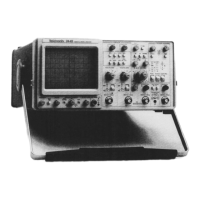
Basic Applications—2445 Operators
speed shortens the length of the zone. The intensified zone
on the A Sweep trace is used to identify the point of
interest to be examined or measured, while the alternate B
Delayed Sweep trace magnifies and displays the intensified
segment. Apparent horizontal magnification of the wave
form occurs as a result of displaying the selected portion of
the A Sweep at a faster B Sweep speed.
Vertical separation of the A and B Sweep traces is
variable using the TRACE SEP control. The control has
enough range to position the B Sweep trace from zero
(overlayed on the A Sweep trace) to three or more divisions
downward from the A Sweep trace.
Time measurements can be readily made on waveforms
by employing the DLY readout and the A REF OR DLY
POS control. Delay time from the A trigger point to the
beginning of the B Sweep is read directly from the DLY
readout in the crt display. After noting a first delay-time
position, a second measurement point can be aligned with
the same reference graticule line, and the new delay time
read. Time difference between the two points is then
determined by computing the difference between the two
delay-time readings. The computed time difference between
the two delay times is more accurate than either of the
delay-time readings.
B Delayed Horizontal Display Mode
Once the point of interest to be examined or measured is
identified, the A Intensified Sweep trace can be eliminated
to provide an uncluttered display for ease of viewing.
Displaying only the B Delayed Sweep (PUSH-B) is accom
plished by pushing in the B SEC/DIV knob after first
establishing the Alternate Horizontal Display mode. Pulling
the B SEC/DIV knob back out returns the A Intensified
trace to the display, if needed to reidentify a measurement
point. Rotating the B SEC/DIV knob back to the same
setting as the A SEC/DIV switch, with the B SEC/DIV
knob pushed in, locks the two knobs together and returns
the Horizontal Display mode back to A Sweep only.
Delta Time Feature with Delayed Sweep
The Delta Time function can be used in any of the
delayed-sweep modes to obtain direct-reading time-
difference measurements. When activated, two separate
B Delayed Sweep intervals are produced in the A Sweep
interval. Delay time for each B Sweep interval is
independently adjustable. The A REF OR DLY POS
control positions one of the delay times, usually referred
to as the Reference intensified zone or the Reference delay.
Positioning of the second delay time, referred to as the
Delta intensified zone or the Delta delay, is accomplished
with the A control.
NOTE
If the Tracking mode of delay-time positioning is
selected (TRACKING/INDEP button in), the A REF
OR DL Y POS control simultaneously moves both the
Reference and the Delta delays equal amounts. The
A control, however, continues to independently
position the Delta delay regardless o f the position o f
the TRACKING/INDEP button.
Delta Time measurements using the A Intensified
Horizontal Display mode are made by simply setting the
start of each intensified zone to the separate measurement
points and noting the A t readout in the crt display. This
method produces the least accurate results, since it is
difficult to determine exact alignment with the measure
ment points.
Much more accurate measurements are possible using
the Alternate Horizontal Display mode. In this mode, a
separate B Delayed Sweep trace is present for each
displayed intensified zone. As explained before, the inten
sified zones are positioned to the points of interest; but
instead of aligning the start of the zones to the measure
ment points, both the Reference and the Delta delays are
adjusted to overlay the two points precisely, using the
respective B Delayed traces. An example application of this
method is given in the following procedure.
This procedure describes the steps necessary to make
time measurements between two time-related pulses applied
on separate input channels. However, the same principles
apply for measuring time differences between successive
pulses, pulse periods, or other time intervals on a single
channel input signal.
1. Preset instrument controls and obtain a baseline trace.
2. Using either probes or cables with equal time delays,
apply a known reference signal to the CH 1 OR X input
connector and apply the comparison signal to the CH 2
input connector.
NOTE
If the repetition rates of the pulses to be measured
are not the same, use the slower repetition-rate signal
as the Trigger SOURCE signal. Using the faster
repetition-rate signal as the Trigger SOURCE will
present multiple triggering-point possibilities during
the period of the slower signal.
6-8
3. Select both CH 1 and CH 2 VERTICAL MODE.

 Loading...