Basic Applications—2445 Operators
4. Set both VOLTS/DIV switches to produce displays
of approximately four to five divisions in amplitude.
5. Press up on the Trigger MODE switch to acquire
the correct AUTO LVL for triggering.
6. Use the Channel 1 and Channel 2 POSITION controls
to vertically center both displays.
7. Set the A SEC/DIV switch to display the measure
ment points of interest within the graticule area.
8. Activate the A Intensified Sweep by pulling out the
B SEC/DIV knob.
9. Activate the Delta Time measurement function by
momentarily pressing the At switch; select the independent
mode of delay-time positioning (TRACKING/INDEP
button out).
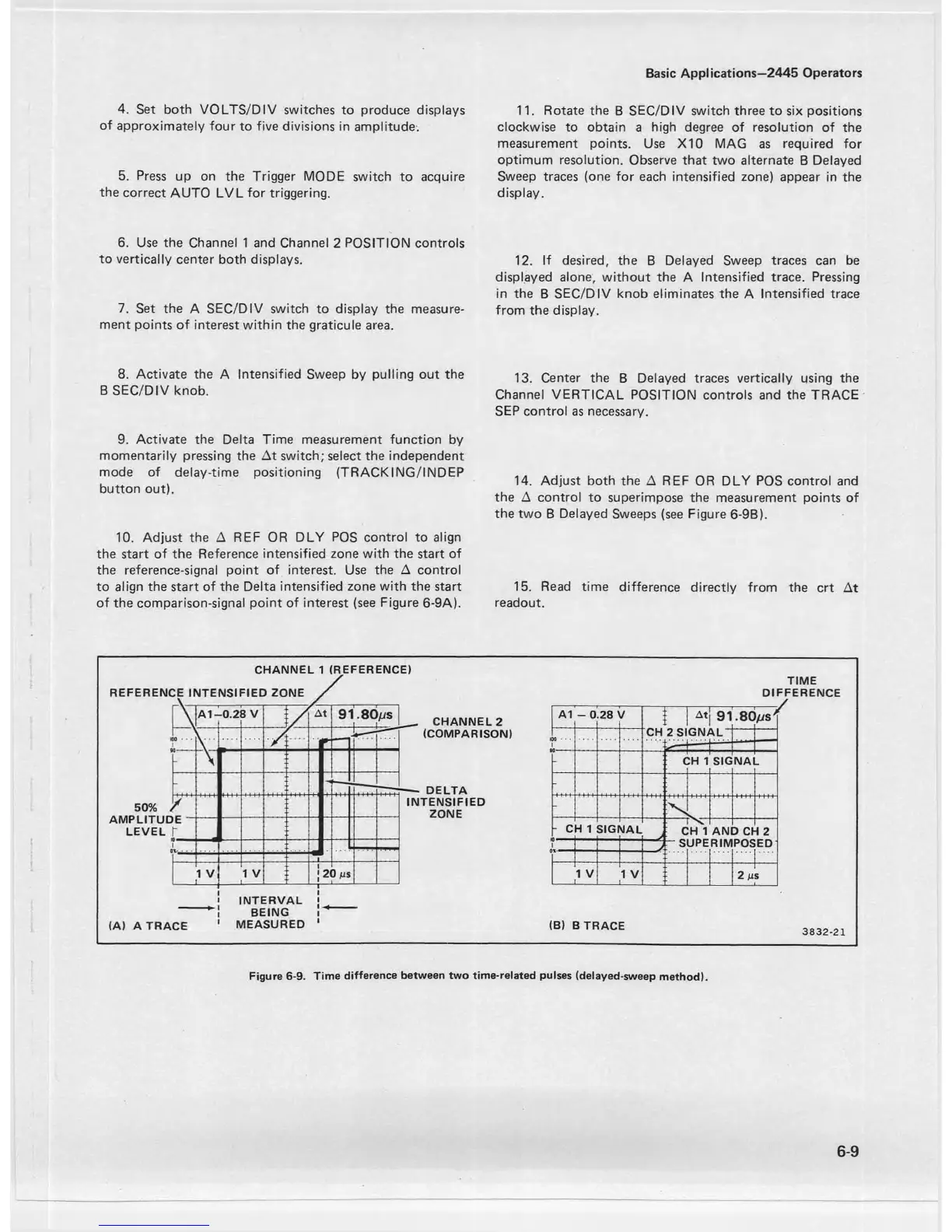
10. Adjust the A REF OR DLY POS control to align
the start of the Reference intensified zone with the start of
the reference-signal point of interest. Use the A control
to align the start of the Delta intensified zone with the start
of the comparison-signal point of interest (see Figure 6-9A).
11. Rotate the B SEC/DIV switch three to six positions
clockwise to obtain a high degree of resolution of the
measurement points. Use X10 MAG as required for
optimum resolution. Observe that two alternate B Delayed
Sweep traces (one for each intensified zone) appear in the
display.
12. If desired, the B Delayed Sweep traces can be
displayed alone, without the A Intensified trace. Pressing
in the B SEC/DIV knob eliminates the A Intensified trace
from the display.
13. Center the B Delayed traces vertically using the
Channel VERTICAL POSITION controls and the TRACE
SEP control as necessary.
14. Adjust both the A REF OR DLY POS control and
the A control to superimpose the measurement points of
the two B Delayed Sweeps (see Figure 6-9B).
15. Read time difference directly from the crt At
readout.
CHANNEL 1 (REFERENCE)
TIME
DIFFERENCE
CH 2 S IG NAL^
r
1 I' —
-
C:h i
SIG
NA
_
-
-
- c d 1 si g r
UAL
: r'sn
: CH 1
AN
3 Cf
f 2
ED
S
UPERIMPOS
1 V
_
__
1 V
__
2 m
s
(B) B TRACE
3 8 3 2 -2 1
6-9
Figure 6-9. Time difference between two time-related pulses (delayed-sweep method).

 Loading...


