I
I
I
I
I
I
I
I
I
REGULATING RANGE SELECTION
The Regulating Range Selector assembly located on
the
rear panel contains
the
Regulating Range Selector Bar and
the line fuse (Figure 1). Verify
that
the selector bar
is
set
for
the
average line voltage being used and
that
the
proper
line fuse
is
installed. To change the regulating range:
1. Disconnect
the
instrument from its power source.
2. Loosen the
two
captive screws
that
hold
the
cover
on
the selector assembly; then pull
to
remove
the
cover.
3. Pull
out
the range selector bar. Select a range from
Table 1 which corresponds
to
the average line voltage
and plug the selector bar
into
the
desired position.
4.
Insert the proper fuse (selected from Table
2)
into its
holder. Push the cover on and tighten the captive
screws.
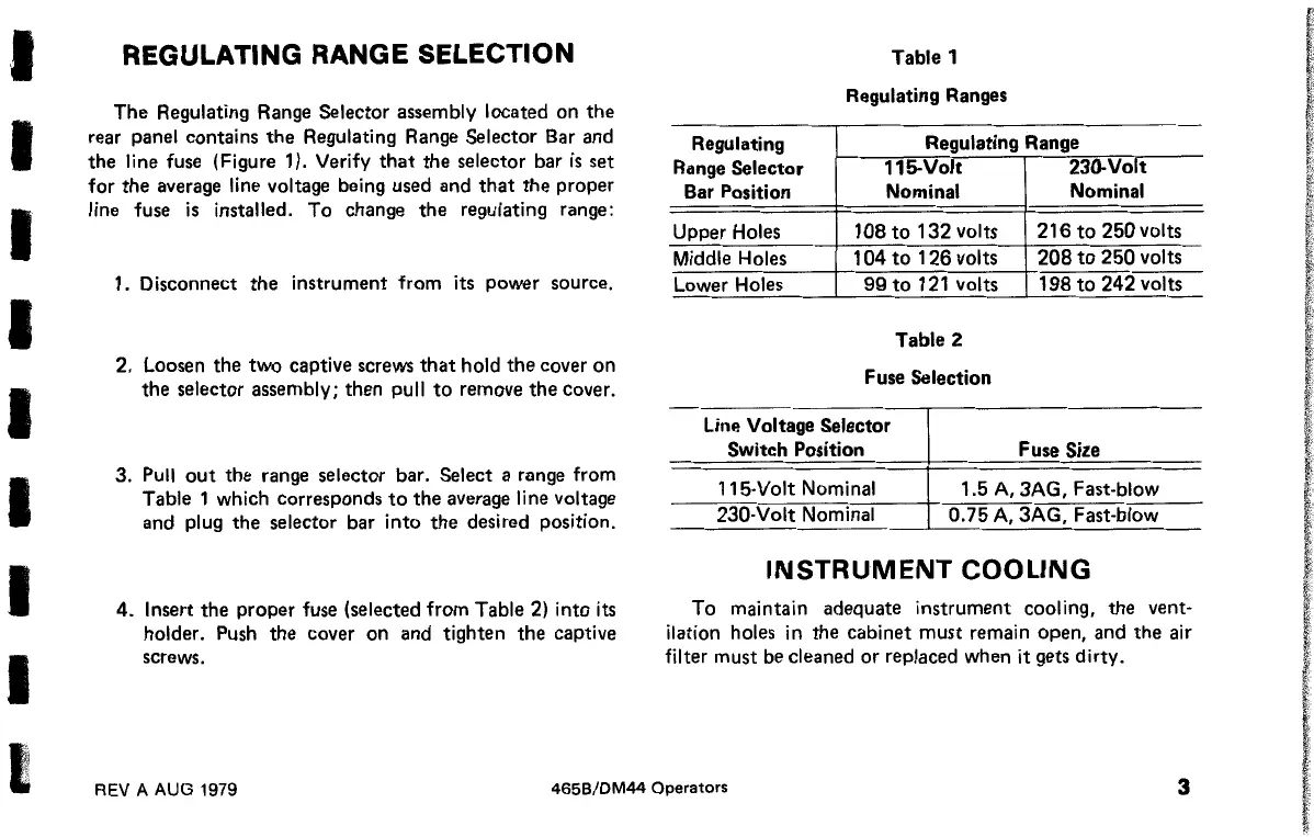
Table 1
Regulating Ranges
Regulating
Regulating Range
Range Selector 115-Volt
230-Volt
Bar Position Nominal
Nominal
Upper Holes 108
to
132
volts
216
to
250
volts
Middle Holes
1
04
to
126
volts
208
to
250
volts
Lower Holes
99
to
121 volts
198
to
242
volts
Table 2
Fuse Selection
Line Voltage Selector
Switch Position Fuse Size
115-Volt Nominal
1.5
A,
3AG, Fast-blow
230-Volt Nominal
0.75
A,
3AG, Fast-blow
INSTRUMENT
COOLING
To maintain adequate instrument cooling, the vent·
ilation holes
in
the cabinet
must
remain open, and the air
filter must be cleaned or replaced when it gets dirty.
REV A AUG 1979
465B/DM44
Operators
3
 Loading...


