5. Slightly readjust the
b.
TIME
control
to
superimpose
the
8
Sweep
display waveform.
6.
Read
the time difference on the DM44 Readout.
7. To determine the pulse repetition rate,
depress
the
DM44
1/TIME
FUNCTION
push
button and
read
the
pulse
repetition rate on the Readout.
Time Difference Between
Two
Time-Related
Pulses
Using
DM44
Obtain a Delayed
Sweep
Display, with controls
set
as
follows:
DM44 FUNCTION
VERT
MODE
HORIZ DISPLAY
A TRIGGER SOURCE
8
(DLY'D)
TRIGGER
SOURCE
8
TIME/DIV
VAR
TIME/DIV
TIME
ALT:
out,
CH
1,
CH
2
AINTEN
CH
1
STARTS AFTER
DELAY
Three or
four
positions more
clockwise than A
TIME/DIV
Calibrated detent position
1.
Using probes or
cables
having equal time delays, con-
nect the reference
signal
to
Channel 1
and
the com-
parison
signal
to
Channel 2 inputs.
2.
Adjust
VOL
TS/DIV
switches
for
vertical displays
of
about
two
divisions.
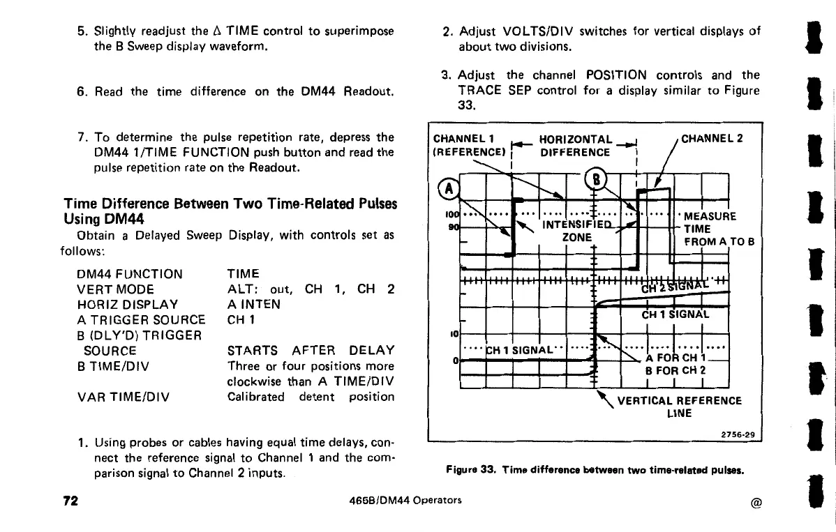
3. Adjust the channel POSITION controls and the
TRACE
SEP
control
for
a display similar
to
Figure
33.
CHANNEL1
REFERENCE)
r-
HORIZONTAL
--.J
I
CHANNEL2
(
<E
10~
10
0
DIFFERENCE
I
"'-..._ I
(j(
I
~
1-
1-
....
1'----
~
•'.!-
I
...
.......
J
...
~-
...
I I
'MEASUR
'
'
INTENSIFIED
.,
TIME
"
ZONE
FR?MA
E
TOB
.I
'*
H'
2
'SIGN~'-
I
CH
1 SIGNAL
I
I I
~H
1
SIGNAL"
....
~
~-·k·FcJe:H·~=
I I
l L
B
FOR
CH
2
_I
1
_l
'VERTICAL
REFERENCE
LINE
2756·29
Figure 33. Time difference between two time-related pulses.
72
465B/DM44 Operators
@
I
I
I
I
I
I
I·
I
I
 Loading...


