1.
Set
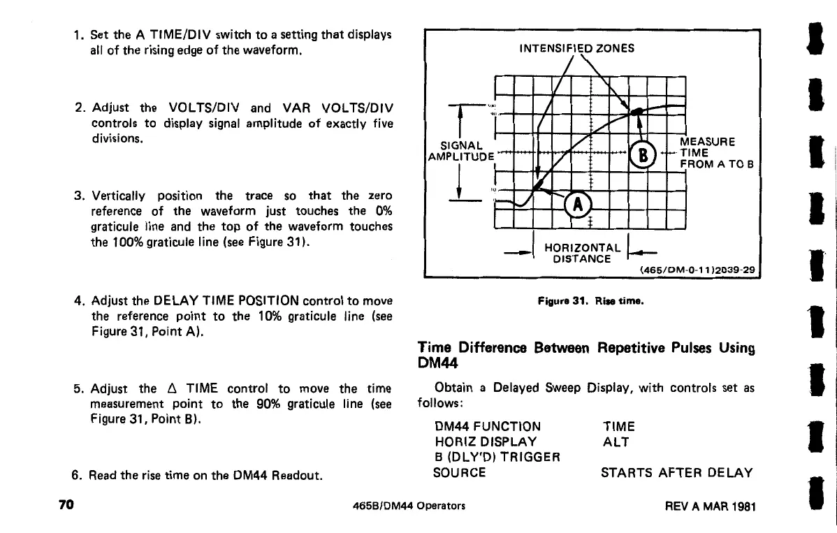
the A TIME/DIV switch
to
a setting
that
displays
all
of
the rising edge
of
the
waveform.
2. Adjust
the
VOL TS/DIV and VAR VOL TS/DIV
controls
to
display signal amplitude
of
exactly five
divisions.
3.
Vertically position the trace so
that
the
zero
reference
of
the
waveform just touches the
0%
graticule line and
the
top
of
the
waveform touches
the 100% graticule line (see Figure 31
).
4. Adjust
the
DELAY TIME POSITION control
to
move
the reference
point
to
the
1
0%
graticule line (see
Figure
31,
Point
A).
5. Adjust
the
t. TIME control
to
move
the
time
measurement
point
to
the
90% graticule line (see
Figure 31, Point
B).
6. Read
the
rise time on
the
DM44 Readout.
INTENSIFIED ZONES
!""'-
l
1/
r·:
I
"'
-
-
j
I
./
~
~
M
SIGNAL
AMPLITUDE
/
/
1
,.~TI
EASURE
ME
_l
l
'-=
!
'{
t-
~
-.(A]
I
Y;
-1
HORIZONTAL
I
DISTANCE
j-
F ROM
ATO
B
(465/DM-0-11
)2039-29
Figura
31.
Rise time.
Time Difference Between Repetitive Pulses Using
DM44
Obtain a Delayed Sweep Display, with controls set
as
follows:
DM44 FUNCTION
HORIZ DISPLAY
B (DLY'D)
TRIGGER
SOURCE
TIME
ALT
STARTS
AFTER
DELAY
70
465B/DM44 Operators
REV A MAR
1981
I
I
I
I
I
I
I
 Loading...


