AFG1000 Series Quick Start User Manual
Protect your instrument from misuse
Check input and output
connectors
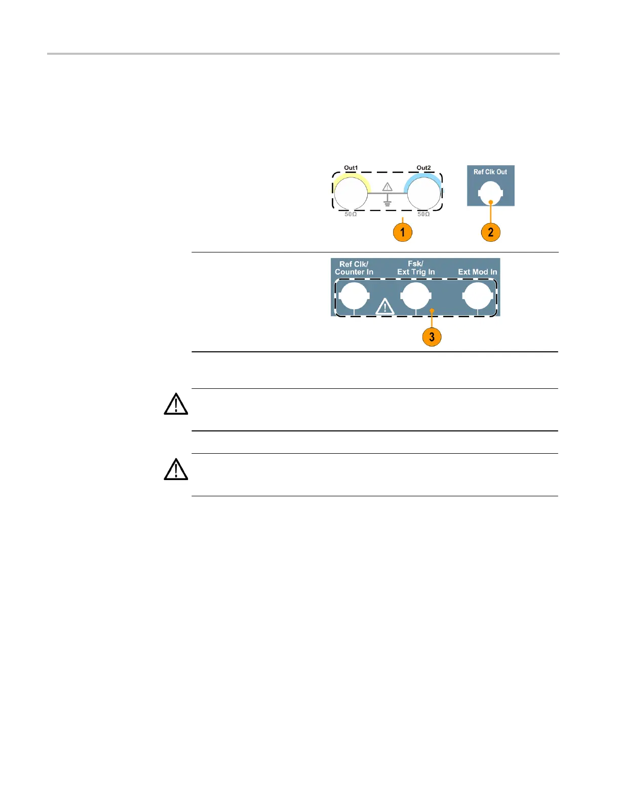
When connecting a cable, be sure to distinguish the input connector from the
output connectors to avoid making wrong connection.
1.
Locate the channel output
on the front panel. Out1
means CH1 output and
Out2 means CH2 output.
2.
Locate the Ref Clk Out
on the rear panel.
3.
Locate the Ref
Clk/Counter In, Fsk/Ext
Trig In and Ext Mod In
connectors on the rear
panel.
CAUTION. The instrument can be damaged when applying external voltages or
shorting the output pins. To avoid damaging the instrument, do not short the output
pins or apply external signals to the output connectors.
CAUTION. The instrument can be damaged when applying excessive inputs over
+5 V to Trigger Input connector. To avoid damaging the instrument, do not apply
excessive inputs over +5 V to Trigger Input connector.
 Loading...


