Instrument front panel, interface, and rear panel
AFG1000 Series Quick Start User Manual
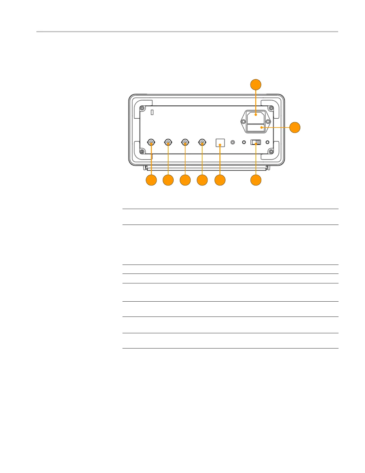
Rear panel
The following illustration shows the rear panel connectors for the instrument.
Item Description
1
Power input: This is where you attached an appropriate power cord to supply
power to the instrument.
2
Fuse: Use the specified fuse according to the voltage scale.
The rating of replaceable fuse:
Voltage Fuse
3
Power line selector: Switch between 110 V / 220 V.
4
USB (type B) connector: This can be used to connect a USB type B controller.
5
Ext Mod In Connector: This is the BNC connector for an external
modulation input. It can be used to input a modulating signal.
6
Fsk/Ext Trig In connector: This is the BNC connector for an FSK/ASK/PSK/external
trigger/burst input.
7
Ref Clk/Counter In connector: This is the BNC connector for an external reference
clock or counter input.
8
Ref Clk Out connector: This is the BNC connector for an external reference clock
output.
 Loading...


