AFG1000 Series Specifications and Performance Verification
3.
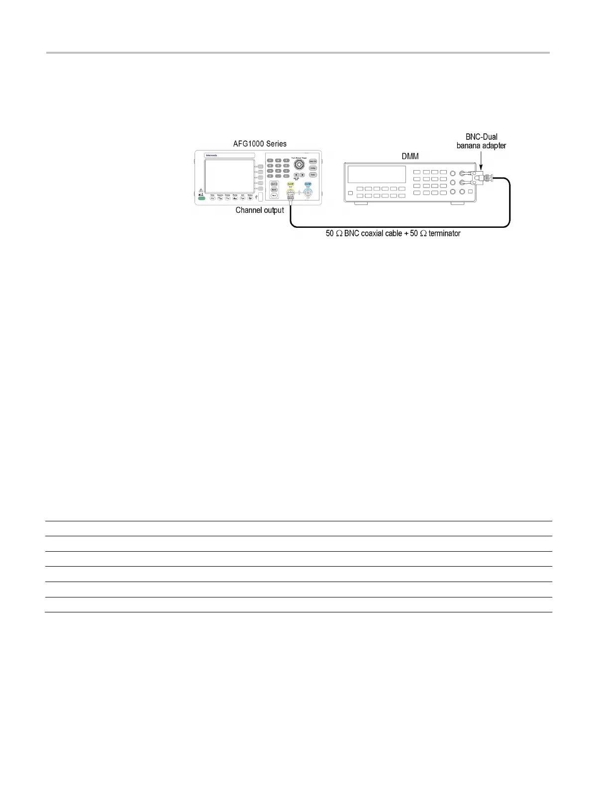
Connect the arbitrary function generator to the DMM as shown in the
following figure. Be sure to connect the 50 Ω terminator to the
arbitrary
function generator Output connector side.
Figure 4: Amplitude tests
4.
Set up the arbitrary function generator as follows:
a.
Push the Sine button on the front panel.
b.
Press the Freq/Period bezel button to choose Freq. The chosen parameter
will be lighted with white background.
c.
Use the numeric keypad or the general purpose knob to set the
frequency to
1 kHz.
d.
Press the Ampl/High bezel button to choose Ampl. The chosen parameter
will be lighted with white background.
e.
Check that the CH1 On/Off front panel button LED is on. If not, then
the channel output is off. Push the CH1 On/Off button to turn it on.
5.
Verify that each amplitude measurement is within the range specified in the
following table. Take care to choose mVrms or Vrms as the voltage unit.
6.
Repeat steps 3 through 5 for the channel 2 output.
Function
Frequency
Amplitude
Measurement
Range
Sine
1.000 kHz
354 mVrms
mVrms
(354 × CF ± 3.89) mVrms
(1.061 × CF ± 0.0110) Vrms
(3.535 × CF ± 0.0357) Vrms
 Loading...


