AFG1000 Series Specifications and Performance Verification
b.
Press the Others bezel button.
c.
Press the Built_in bezel button, then Others bezel button. Select DC.
d.
Press the Offset/Low bezel button to choose Offset. The chosen parameter
will be lighted with white background.
e.
Use the numeric keypad or the general purpose knob to set the offset
value.
f.
Check that the CH1 On/Off front panel button LED is on. If not, then the
channel output is off. Push the CH1 On/Off button
to turn it on.
5.
Verify that each offset measurement is within the range specified in the
following table.
6.
Repeat steps 3 through 5 for the channel 2 output.
Function Offset Measurement
Range
DC + 5.000 Vdc Vdc (5.000 × CF ± 0.051) Vdc
DC + 2.000 Vdc Vdc (2.000 × CF ± 0.021) Vdc
DC + 1.000 Vdc Vdc (1.000 × CF ± 0.011) Vdc
DC
0.000 Vdc
Vdc
± 0.001 Vdc
DC - 1.000 Vdc Vdc (- 1.000 × CF ± 0.011) Vdc
DC - 2.000 Vdc Vdc (- 2.000 × CF ± 0.021) Vdc
DC - 5.000 Vdc Vdc (- 5.000 × CF ± 0.051) Vdc
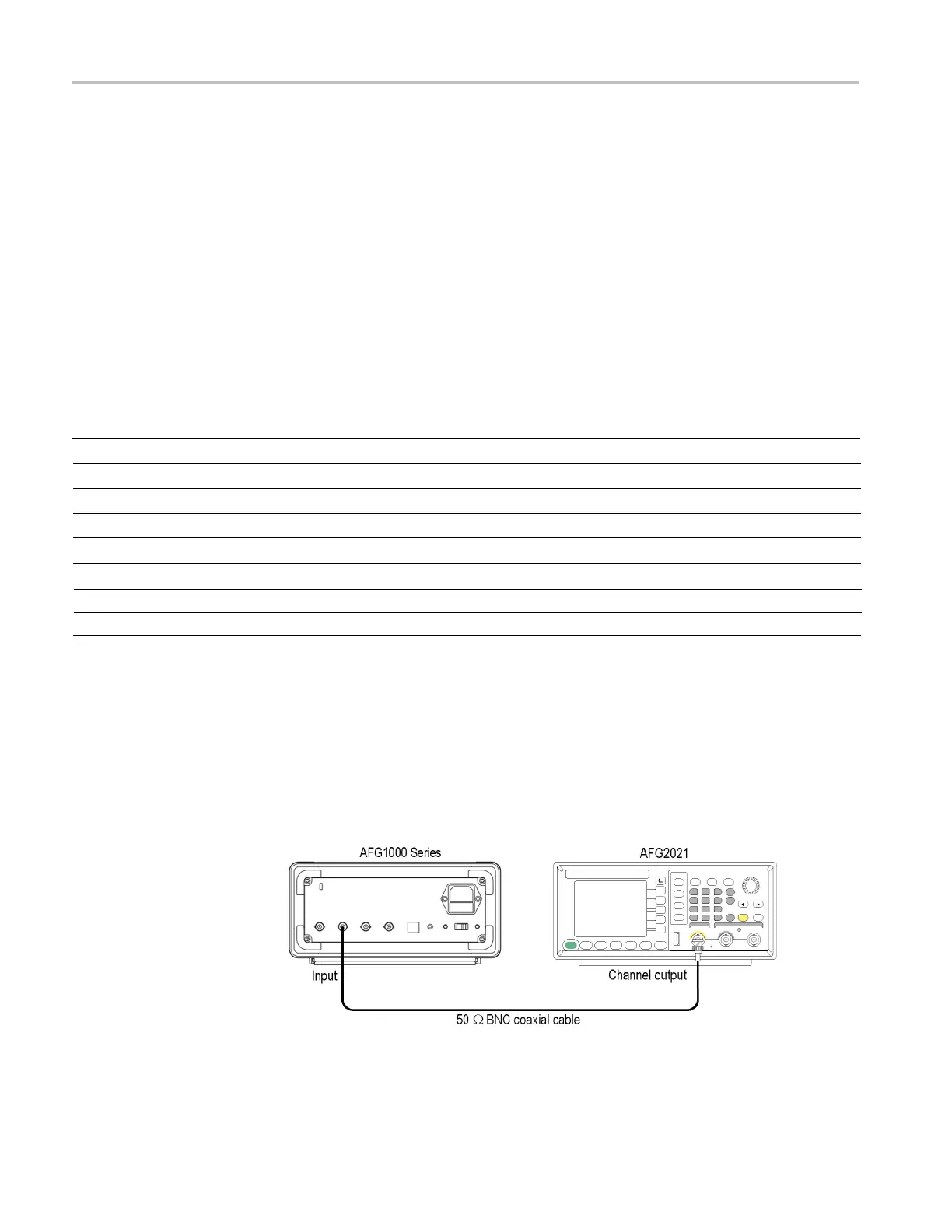
Counter test
This test verifies the frequency counter accuracy of the instrument. Only one
frequency point is required to be checked.
1.
Connect the Ref Clk/Counter In connector on the rear panel of the AFG1000
Series to the AFG2021 signal generator as shown in
the following figure.
Figure 7: Counter tests
 Loading...


