Pinpoint trigge
rs
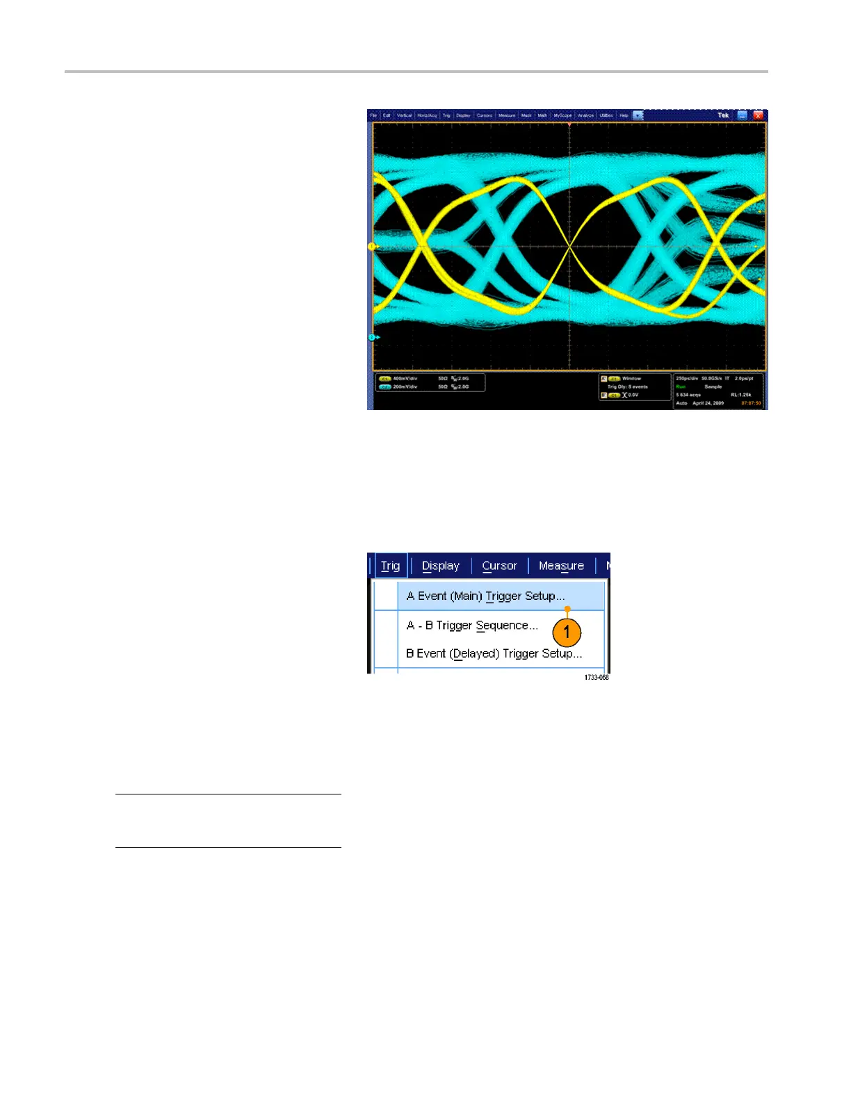
10. In this example, a DDR3 DQ S signal is
on Ch 1 and the DQ signal is on Ch 2.
The i nstrumen
t is in R un Mode with
Display Mode set to Infinite Persistence.
The instrument trigger setup was as
follows:
A-Event Window trigger on Ch 1
to detect the DDR3 DQ S Write
condition.
B-Event Edge trigger on Either slope
on Ch 1 to trigger on the DQS (clock)
edges.
A->B Sequence s et to Trig on the
nth Event.
B Scan Enab
led with Start Event
= 1, End Event = 8, and Mode =
Sequential.
The data ey
es are formed by the DQ
signal on Ch 2.
Triggering on a parallel bus
Locate problems by triggering on a parallel bus. MSO instruments can use digital channels as components of a parallel bus.
1. Set up a parallel bus. (See page 53,
Setting up a bus.) Se lect Trig > A Event
(Main) Trigger Setup....
2. Select the A Event tab.
3. Select the Bus Trigger Type.
4. Select the bus to trigger on.
NOT
E. Clocked buses will only appear in
the drop down list if the clock source is set
to Ch4.
78 MSO/DPO70000DX, MSO/DPO70000C, DPO7000C, and MSO /DP O5000 Series U ser Manual
 Loading...


