40
Phaser 740 and 750 Color Printers
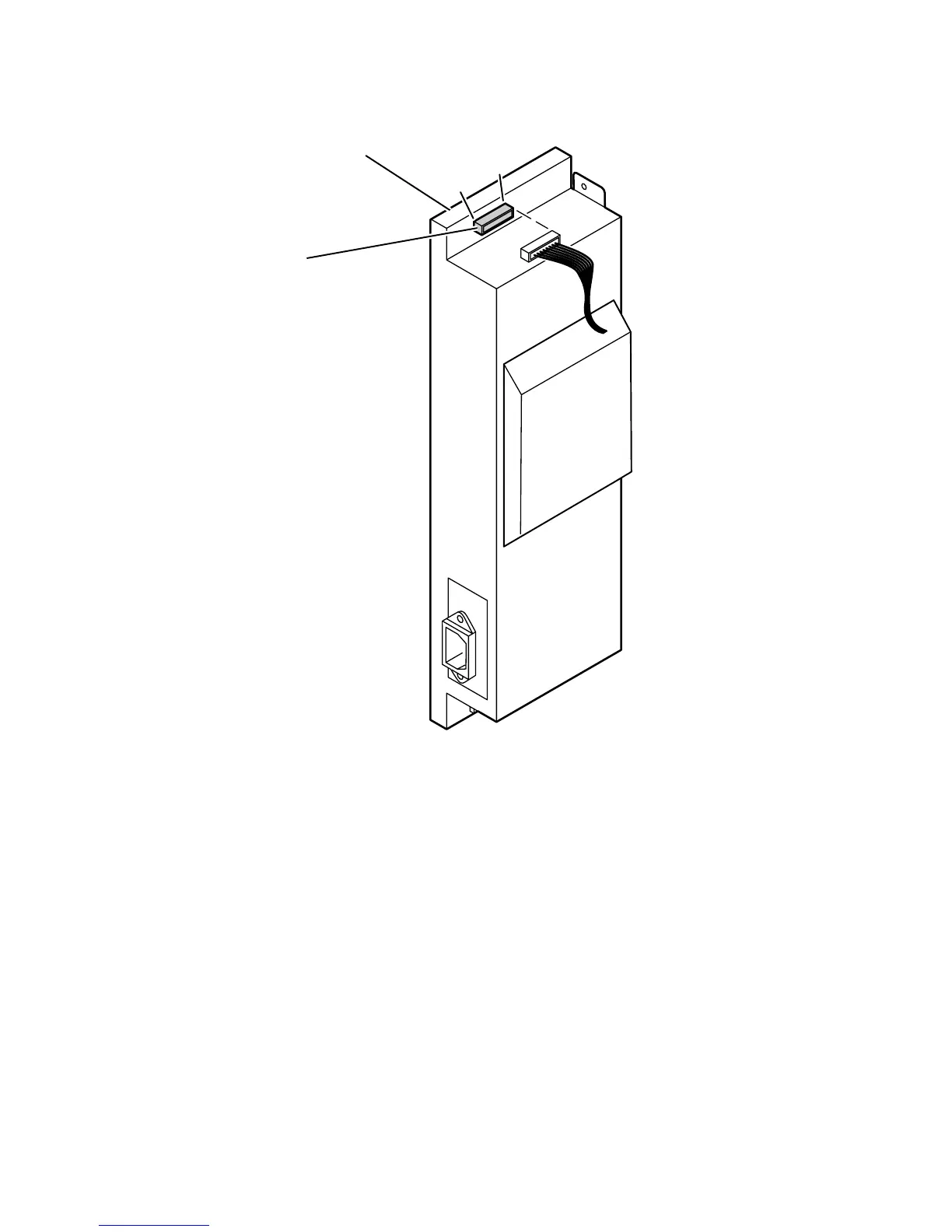
DC Output:
With the VOM set to measure DC voltages, measure voltages at CN301
for +5 VDC and +24 VDC. If the voltage is not correct, replace the power supply. The
following illustration shows the test points.
If DC voltages are not being output by the power supply, proceed to the next step,
“Inspecting the power supply fuses” on page 41.
If the +5 and +24 VDC voltages measure correctly, but the printer does not operate
correctly, then proceed to the topic, “Safety interlocks” on page 41.
Measuring the DC voltages (test points)
3102-06
CN 301
Pin 9 -+24 V
Pin 8 -GND
Pin 7 -GND
Pin 6 -GND
Pin 5 -+24 V
Pin 4 -+24 V
Pin 3 -GND
Pin 2 -+5 V
Pin 1 -+5 V
Power supply
9
1
 Loading...