Analyzing a differential communication signal
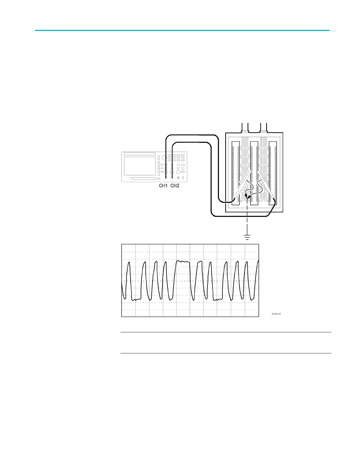
You are having intermittent problems with a serial data communication link, and
you suspect poor signal quality. Set up the oscilloscope to show you a snapshot
of the serial data stream so you can verify the signal levels and transition times.
Because this is a differential signal, you use the Math function of the oscilloscope
to view a better representation of the waveform.
NOTE. Be sure to first compensate both probes. Differences in probe
compensation appear as errors in the differential signal.
To activate the differential signals connected to channel 1 and to channel 2,
follow these steps:
1. Push the 1 (channel 1 menu) button and set the Probe ► Voltage ►
Attenuation option to 10X.
2. Push the 2 (channel 2 menu) button and set the Probe ► Voltage ►
Attenuation option to 10X.
3. If using P2220 probes, set their switches to 10X.
4. Push the Autoset button.
Application examples
TBS1000B and TBS1000B-EDU Series Oscilloscopes User Manual 47

 Loading...


