6. Push the Multipurpose knob to select Time.
7. Push the Source side-menu button. A pop-out menu should appear showing a
scroll-able list of the available sources.
8. Turn the Multipurpose knob to highlight Ch1.
9. Push the Multipurpose knob to select Ch1.
10. Push the Cursor 1 option button.
11. Push the Cursor 1 option button.
12. Turn the Multipurpose knob to place a cursor on the active edge of the chip-
select signal.
13. Push the Cursor 2 option button.
14. Turn the Multipurpose knob to place the second cursor on the data output
transition.
The Δt readout in the Cursor Menu is the propagation delay between the
waveforms. The readout is valid because the two waveforms have the same
horizontal scale (seconds/division) setting.
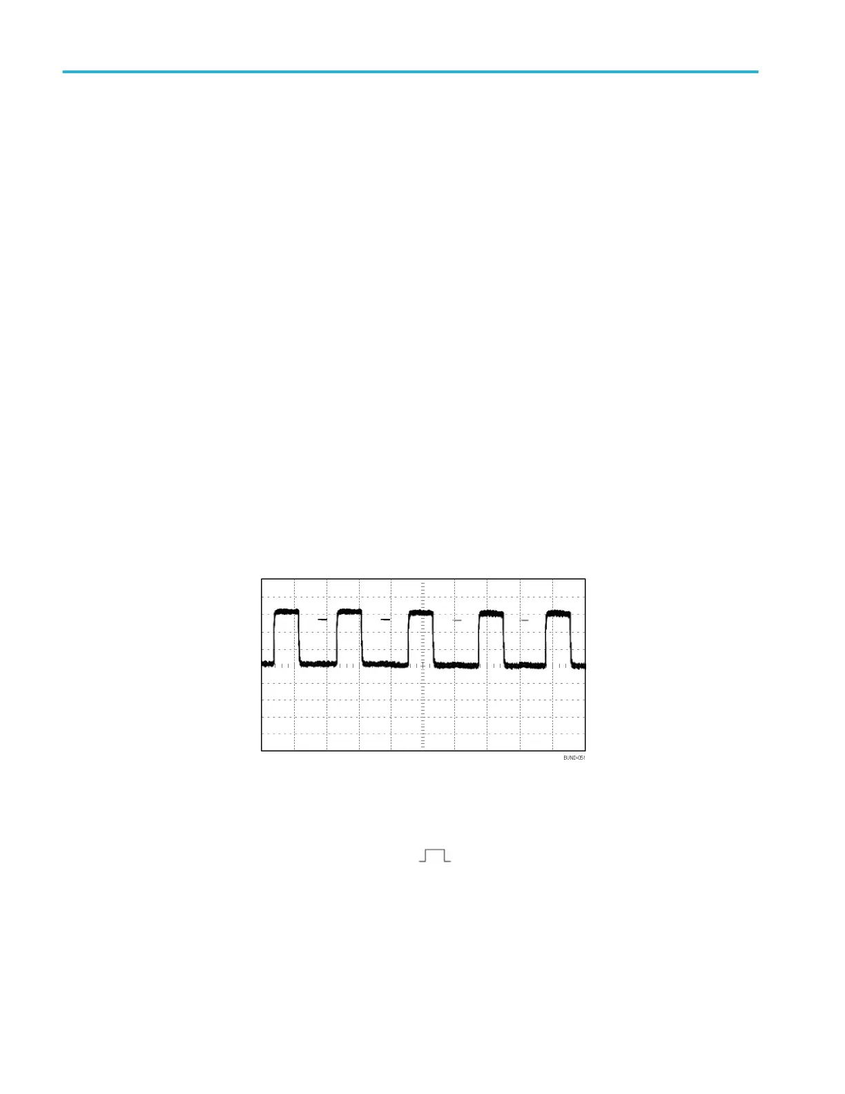
Triggering on a specific pulse width
To set up a test for pulse width aberrations, follow these steps:
1. Push the Autoset button to trigger a stable display.
2.
Push the single cycle option button in the Autoset Menu to view a
single cycle of the signal, and to quickly take a Pulse Width measurement.
3. Push the Trigger Menu button to see the Trigger Menu.
4. Push Type.
5. Turn the Multipurpose knob to highlight Pulse from the pop-out menu. Push
the knob to select the choice
6. Push Source.
Application examples
42 TBS1000B and TBS1000B-EDU Series Oscilloscopes User Manual
 Loading...


