Performance Tests
TDS 500B, 600B and TDS 700A Service Manual
4–39
b. Modify the initialized front-panel control settings:
H Do not adjust the vertical position of any channel during this
procedure.
H Set the horizontal SCALE to 500 ps.
H Press SHIFT; then press ACQUIRE MENU.
H Press the main-menu button Mode, and then press the side-menu
button Average 16.
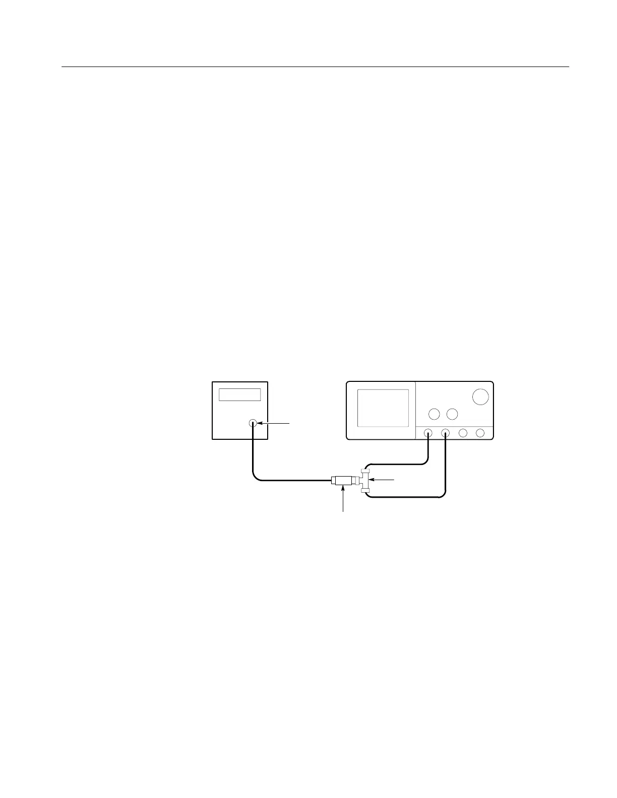
c. Hook up the test-signal source:
H Connect the sine wave output of a sine wave generator (item 19 or,
optionally, 25) to a 50 W precision coaxial cable followed by a 50 W
termination, and a dual-input coupler. See Figure 4–10.
H Connect the coupler to both CH 1 and CH 2. See Figure 4–10.
Sine Wave
Generator
Dual Input
Coupler
Digitizing Oscilloscope
50 Terminator
Output
Figure 4–10: Initial Test Hookup
2. Confirm all four channels (CH 1 through CH 4 (AX2 on the TDS520B,
620B, 680B, and 724A)) are within limits for channel delay:
a. Set up the generator: Set the generator frequency to 250 MHz and the
amplitude for about six divisions in CH 1.
Hint: As you are adjusting the generator amplitude, push SET LEVEL
TO 50% frequently to speed up the updating of the waveform amplitude
on screen.
b. The horizontal SCALE should already be set to 500 ps. On the TDS
784A and TDS 600B, now set it to 200 ps. On the TDS 520B, 540B,
 Loading...


