Typical Characteristics
TDS 500B, 600B and TDS 700A Service Manual
1–27
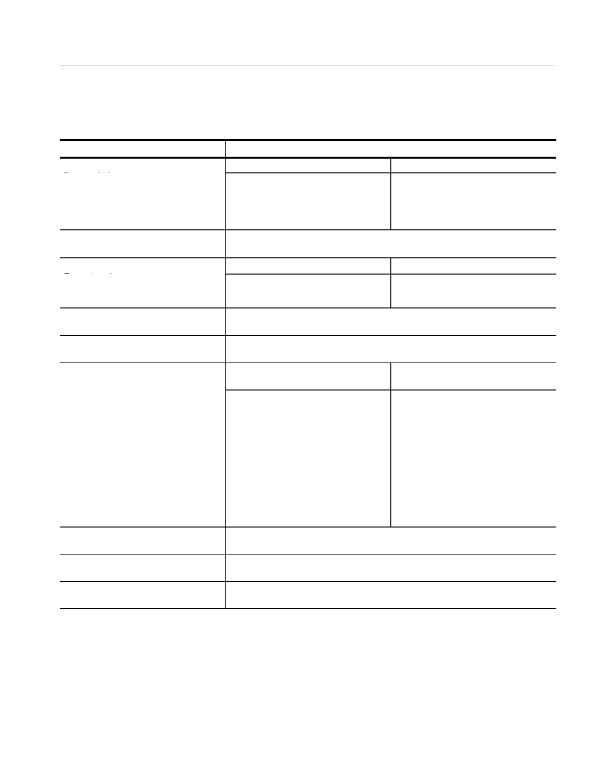
Table 1–16: Typical Characteristics — Triggering System
Name Description
,
L
o
s
o
,
Trigger Source Accuracy
C Co
(for signals having rise and fall times
≥ 20 ns)
Any Channel
Auxiliary
±((2% × | Setting – Net Offset |)
+ (0.3 div × Volts/div Setting ) + Offset
Accuracy)
Not calibrated or specified
Input, Auxiliary Trigger
The input resistance is ≥1.5 kW; the maximum safe input voltage is
±20 V (DC + peak AC).
Tr
r P
n
rr
r,
Acquisition Mode Trigger-Position Error
1,2
d
Tr
r
n
Sample, Average
Envelope
±(1 Waveform Interval + 1 ns)
±(2 Waveform Intervals + 1 ns)
Holdoff, Variable, Main Trigger
For all Time/Division ranges, the minimum holdoff is 250 ns and the maximum holdoff is
12 seconds. The minimum resolution is 8 ns for settings ≤ 1.2 ms.
Lowest Frequency for Successful Operation
of “Set Level to 50%” Function
30 Hz
S
n
v
,
d
Tr
r,
up
d
Trigger Source
Typical Signal Level for Stable
Triggering
AC
Noise Reject
High Frequency Reject
Low Frequency Reject
Same as the DC-coupled limits for
frequencies above 60 Hz. Attenuates
signals below 60 Hz.
Three times the DC-coupled limits.
One and one-half times the DC-coupled
limits from DC to 30 kHz. Attenuates
signals above 30 kHz.
One and one-half times the DC-coupled
limits for frequencies above 80 kHz.
Attenuates signals below 80 kHz.
Sensitivities, Logic Trigger and Events
Delay, DC Coupled
4
1.0 division, from DC to 500 MHz, at vertical settings > 10 mV/div and ≤ 1 V/div at the
BNC input
Sensitivities, Pulse-Type Runt Trigger
5
1.0 division, from DC to 500 MHz, at vertical settings > 10 mV/div and ≤ 1 V/div at the
BNC input
Sensitivities, Pulse-Type Trigger Width and
Glitch
6
1.0 division, at vertical settings > 10 mV/div and ≤ 1 V/div at the BNC input
 Loading...


