Tutorial
2–16
TDS 500B, TDS 600B, & TDS 700A User Manual
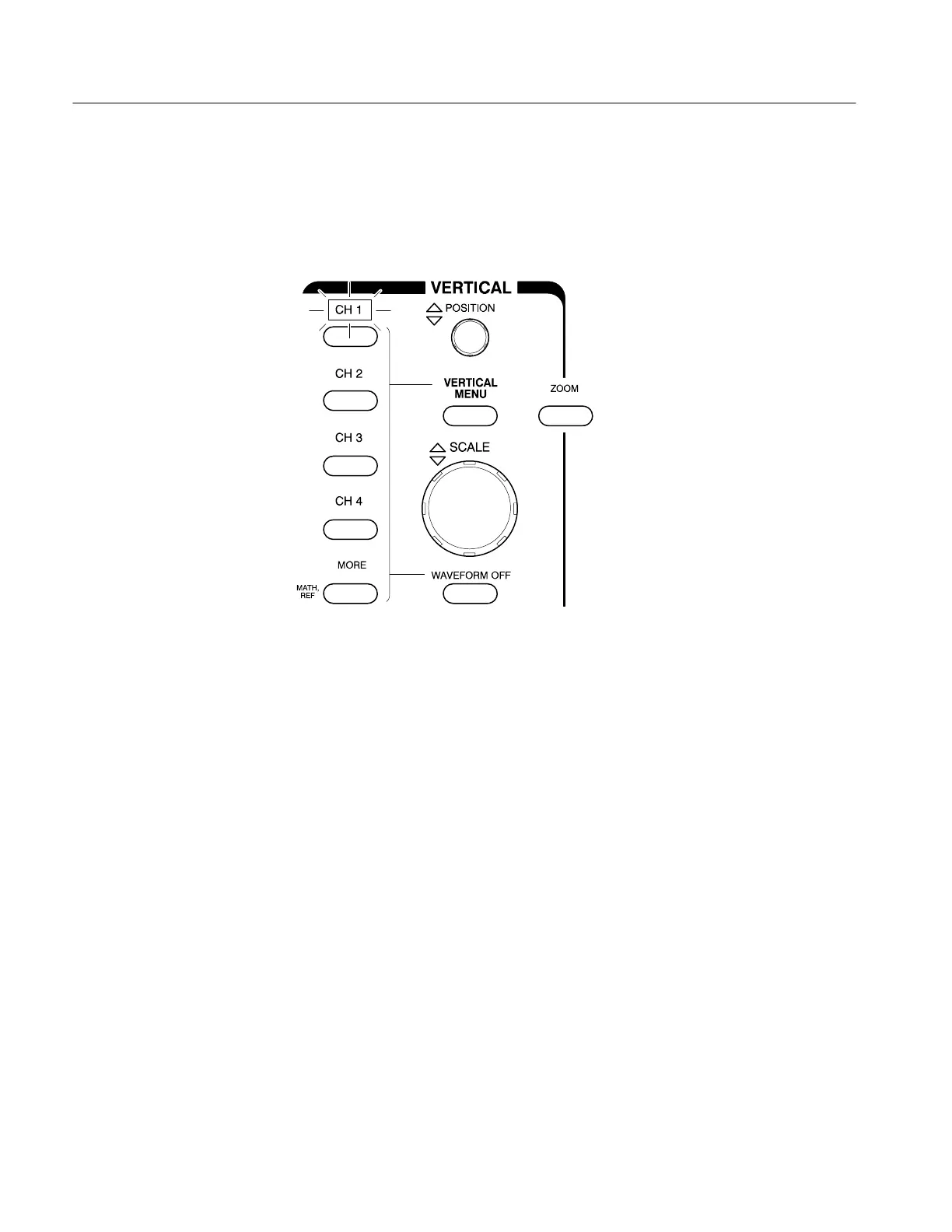
The VERTICAL section of the front panel contains the channel selection
buttons. These buttons are CH 1, CH 2, CH 3, CH 4, and MORE. (See Fig-
ure 2–11.) (CH 3 and CH 4 will be replaced by AUX1 and AUX2 on some
models; see Default Model on page xii and Differences by Model on page 1–2.)
Figure 2–11: The Channel Buttons and Lights
Each of the channel (CH) buttons has a light behind its label. Right now, the
CH 1 light is on. That light indicates that the vertical controls are set to adjust
channel 1. Do the following steps to add a waveform to the display:
1. If you are not continuing from the previous example, follow the instructions
on page 2–9 under the heading Setting Up for the Examples.
2. Press SETUP ➞ Recall Factory Setup (main) ➞ OK Confirm Factory
Init (side).
3. Press AUTOSET.
4. Press CH 2.
The display shows a second waveform, which represents the signal on
channel 2. Since there is nothing connected to the CH 2 input connector, this
waveform is a flat line. There are several other important things to observe:
The channel readout on the display now shows the settings for both Ch1
and Ch2.
There are two channel indicators at the left edge of the graticule. Right
now, they overlap.
Add a Waveform
 Loading...


