Acquiring and Displaying Waveforms
TDS 500B, TDS 600B, & TDS 700A User Manual
3–5
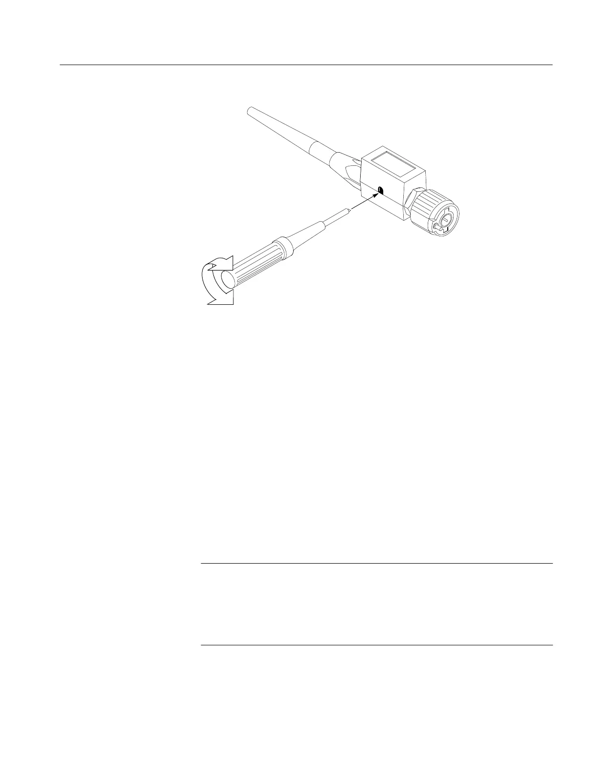
Figure 3–2: P6139A Probe Adjustment
To ensure proper coupling of your input signals to the oscilloscope, consider the
following points when you use 50 W coupling with any channel:
The oscilloscope does not accurately display frequencies under 200 kHz if
AC coupling is selected.
The oscilloscope reduces the maximum volts/division setting for the channel
to 1 V from 10 V (to 10 V from 100 V with a X10 probe attached), since
input amplitudes appropriate for the higher settings would overload the
50 W input.
The oscilloscope switches to 50 W and disables AC coupling (and switches
coupling to DC if AC is selected) if you connect an active probe, such as the
P6245 probe. Such probes also reduce the maximum volts/div to 10 V as just
described. This behavior results in 50 W, nonAC coupling, which is
appropriate for such probes.
NOTE. If you remove an active probe, the oscilloscope does not switch coupling
back to 1 M (nor AC if it was previously selected). Nor does the oscilloscope,
when you restore 1 M coupling, return to a volts/division setting that was
reduced due to the 50 selection. In general, you must set channel scale, input
coupling, and impedance appropriate for your input coupling scheme. Be sure to
switch to 1 M for any input signal not from a 50 system.
Input Impedance
Considerations
 Loading...


