Typical Characteristics
2–32
TDS 500D, TDS 600C, TDS 700D & TDS 714L Performance Verification and Specifications
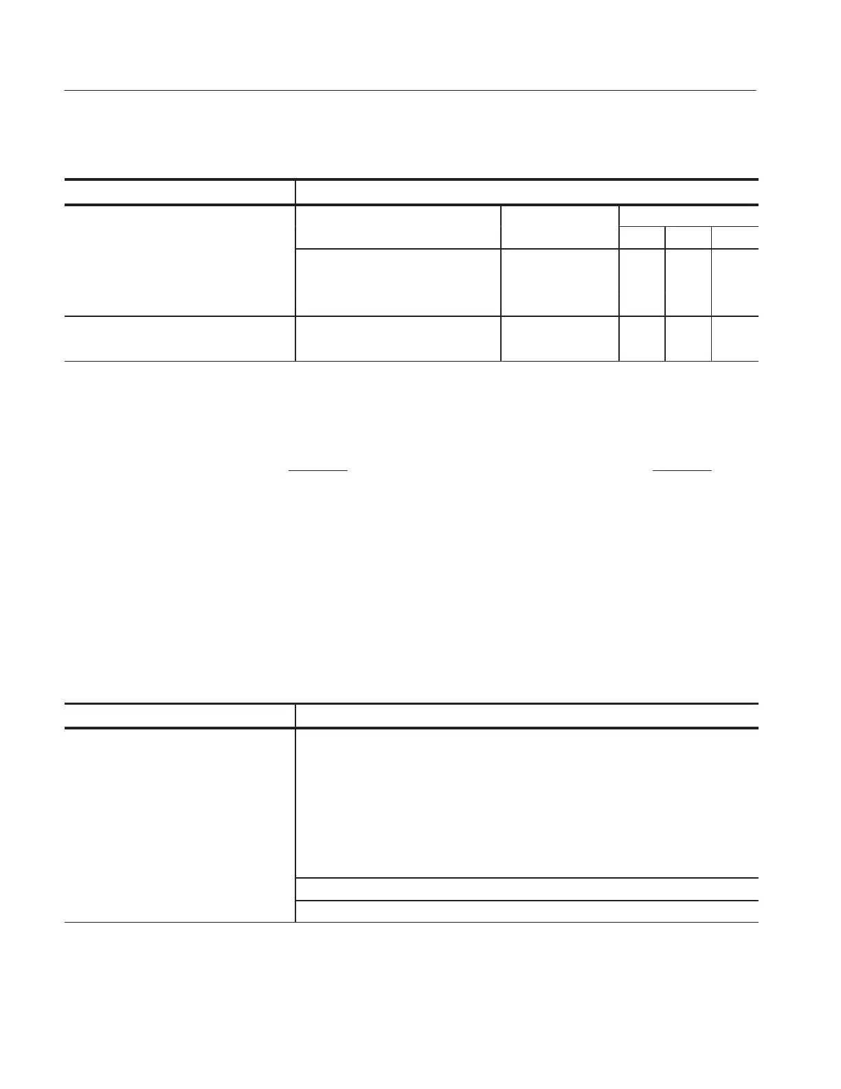
Table 2–16: Typical characteristics — Signal acquisition system (cont.)
Name Description
Step Response Settling Errors Settling error (%)
3
at
Volts/Div setting ± Step amplitude 20 ns 100 ns 20 ms
1 mV/div – 100 mV/div ≤2 V ≤0.5% ≤0.2% ≤0.1%
101 mV/div – 1 V/div ≤20 V ≤1.0% ≤0.5% ≤0.2%
1.01 V/div – 10 V/div ≤200 V ≤1.0% ≤0.5% ≤0.2%
Step Response Settling Errors 10 mV/div – 100 mV/div ≤1.5 V ≤0.5% ≤0.2% ≤0.1%
TDS 694C/794D
101 mV/div – 1 V/div
≤3 V ≤1.0% ≤0.5% ≤0.2%
1
The limits given are for the ambient temperature range of 0_C to +30_C, TDS 694C 4_C to +30_C. Reduce the upper
bandwidth frequencies by 5 MHz for the TDS 600C or by 2.5 MHz for the TDS 500D/700D/714L for each _C above +30_C. For
the TDS 694C and TDS 794D reduce the upper bandwidth frequencies by 10 MHz for each _C above +30_C.
2
The numbers given are valid 0_C to +30_C and will increase as the temperature increases due to the degradation in
bandwidth. Rise time is calculated from the bandwidth. It is defined by the following formula:
Note that if you measure rise time, you must take into account the rise time of the test equipment (signal source, etc.) that
you use to provide the test signal. That is, the measured rise time (RT
m
) is determined by the instrument rise time (RT
i
) and
the rise time of the test signal source (RTgen) according to the following formula:
TDS 600C Rise Time (ns) +
450
BW (MHz)
RT
m
2
+ RT
i
2
) RT
gen
2
TDS 500Dń694Cń700D Rise Time (ns) +
400
BW (MHz)
3
The values given are the maximum absolute difference between the value at the end of a specified time interval after the
midlevel crossing of the step and the value one second after the midlevel crossing of the step, expressed as a percentage
of the step amplitude.
Table 2–17: Typical characteristics — Time base system
Name Description
Accuracy, Delta Time Measurement
(TDS 500D/700D Option 1G and
TDS 714L)
Conditions for accuracy listed at right
are: Single Shot, Sample or HiRes
mode with Full Bandwidth selected.
The limits are given in the following table for signals having amplitude greater than
5 divisions, reference level = 50%, filter set to (sinX/X), acquired at 5 mV/div or greater.
For the TDS 500D/700D Option 1G and the TDS 714L, pulse duration < 10 div. Channel
skew not included.
For the Single Shot condition, 1.4 ≤ T
r
B S ≤ 4, where
S is the sample rate and T
r
is the displayed rise time.
Extra error in the measurement will occur for two-channel measurements due to
channel-to-channel skew. This is described elsewhere in these specifications.
Time measurement accuracy
±((0.15 B sample rate) + (25 ppm × | Reading |))
Artisan Technology Group - Quality Instrumentation ... Guaranteed | (888) 88-SOURCE | www.artisantg.com
 Loading...


