6
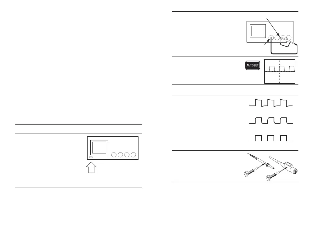
3. Connect the oscilloscope probe
to channel 1. Attach the probe
tip and reference lead to the
PROBE COMP connectors.
CH 1
PROBE COMP
4. Push the AUTOSET button.
You should see a square wave
in the display (approximately
5 V at 1 kHz).
Probe Compensation
5. Check the shape of the dis-
played waveform.
Overcompensated
Compensated correctly
Undercompensated
6. Adjust your probe if necessary
to achieve correct compensa-
tion.
L
5
TDS3000B Initial Setup
The following procedures describe how to quickly verify
that the oscilloscope is powering up and functioning
correctly, compensate passive probes using the built-in
compensation signal, and run the signal path compensa-
tion (SPC) routine for maximum signal accuracy.
H You should perform all initial setup procedures the
first time you use the oscilloscope.
H You should perform the probe compensation
procedure whenever you attach a passive probe for
the first time to any input channel.
H You should run the signal path compensation routine
whenever the ambient temperature changes by 10_ C
or more.
Functional Check
1. Connect the oscilloscope power cable
2. Turn on the oscilloscope. Wait
for the confirmation that the
oscilloscope has passed all
self-tests.
On/Standby
button
 Loading...


