Product Overview
This chapter briefly describes the product controls and connectors of the logic
analyzers. Refer to the online help for detailed operating information for the
logic analyz
er.
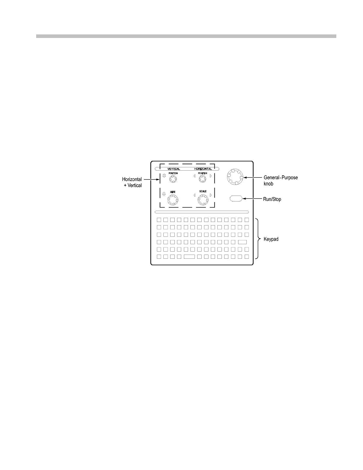
Front Panel Controls
You ca n use t h
e front panel controls to operate the logic analyzer. You can also
attach an external keyboard, monitor, and mouse to operate the logic analyzer.
You c an use t
he front panel keys as an alternative to an external keyboard. Most
keys and key combinations are available using the front panel. (See Figure 5.)
Figure 5: Logic analyzer front panel
External Connectors
Use the external connectors on the rear panel of the logic analyzer to connect
extern
al accessories. (See Figure 2 on page 3.)
Use the four front panel BNC connectors to send signals between the logic
analy
zer and other instruments. For example, use the iView cable to connect
the logic analyzer to an oscilloscope.
TLA5000 Series Logic Analyzer Installation M anual 9

 Loading...


