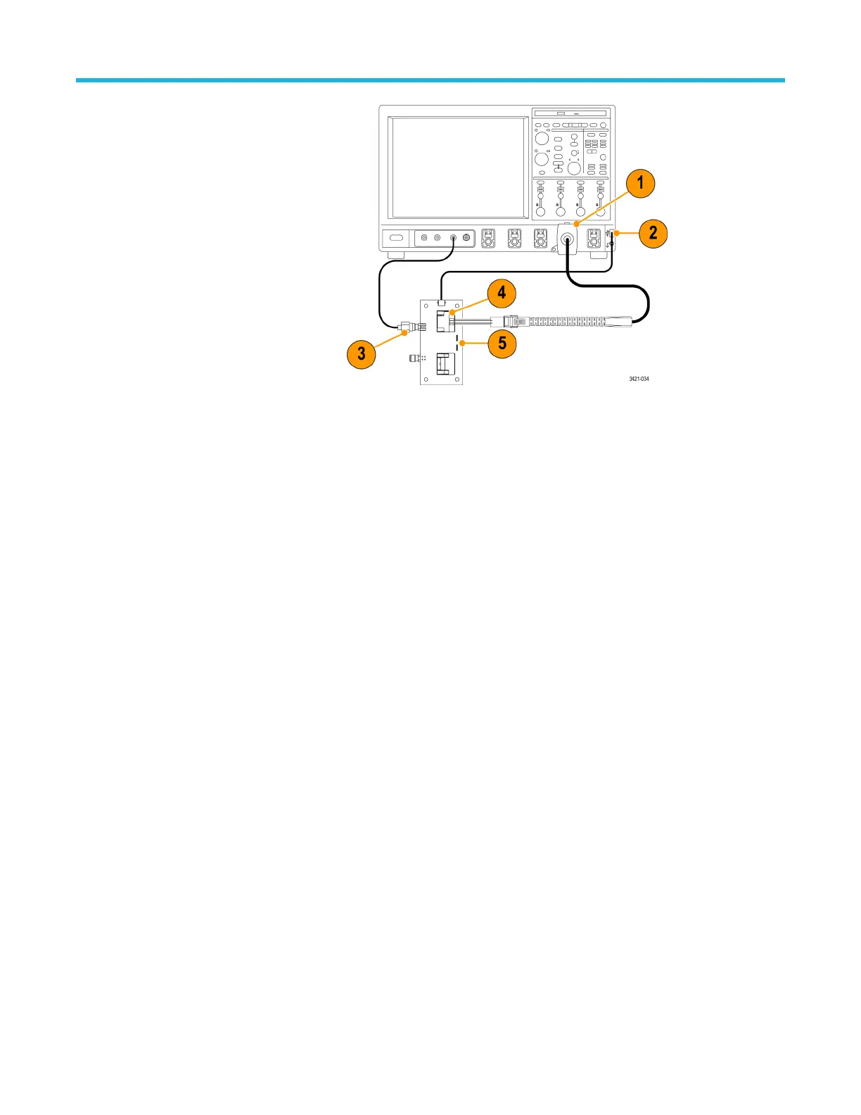
Test setup with the P77DESKEW
Fixture Test setup with the TEK-
CDA accessory
Connect the probe to any channel
(1-4) of the oscilloscope
(connection to CH4 is shown). Set
the oscilloscope to display the
connected channel.
Connect the USB cable assembly
supplied with the P77DESKEW
TEK-CDA fixture between the
USB connector on the fixture
board and a USB connector on
the host oscilloscope. Several
white LEDs under the fixture
Port1 and Port2 probe tip clamps
will light up when the fixture is
attached to USB power.
Connect an SMA cable from the
FAST EDGE output connector on
the oscilloscope to the A input of
the Probe Deskew Fixture.
Connect a P7700 TDP7700 Series
probe tip to either the Port1 or
Port2 on the P77DESKEW TEK-
CDA fixture. If a TekFlex solder-in
tip is used to make this
connection, its tip input should
be inserted into the plastic clamp
of the deskew fixture port. This is
done by compressing the spring-
loaded clamp, inserting the probe
tip input into the clamp, and then
releasing the clamp so that it
locks the connection.
An additional set of green LEDs
will light up under the probe tip
clamp when the solder-down
probe tip is properly inserted into
the clamp.
Finally, connect the TekFlex
connector at the end of the probe
main cable to the probe tip
inserted into the deskew fixture
port. An LED on the probe tip will
also light up when the tip is
properly inserted into the TekFlex
connector of the probe.
If a P77BRWSR TDP77BRWSR tip
is used instead of a solder-down
tip to make connection to the
Deskew Fixture, the TekFlex
Functional check and calibration
P7700 Series TriMode™ Probes 10

 Loading...


