SSG000\08
12-2005
32
poste a monte: a questo scopo il relè possiede due identici circuiti
d'uscita di blocco, elettricamente separati, ma funzionanti in
modo identico.
Il relè SSG esegue un controllo permanente dell'efficienza del
filo pilota relativo ai circuiti di blocco. Precisamente il circuito
d'uscita di blocco emette periodicamente degli impulsi, di durata
insufficiente per essere rilevati dal circuito d'entrata di blocco
della protezione a monte quali effettivi segnali di blocco, ma
sufficienti per testimoniare la continuità del collegamento. Inoltre
viene identificata la presenza permanente (o di durata superiore
a un tempo limite prefissato) del segnale di blocco, che testimonia
un eventuale corto circuito nel filo pilota o nel circuito d'uscita
delle protezioni a valle.
Nel caso in cui si debba realizzare la funzione di blocco in
collegamento con altri relè non appartenenti alla serie S, occorre
rinunciare al circuito dedicato sopra descritto e utilizzare un
circuito d'entrata digitale e/o un circuito d'uscita con relè: questi
circuiti possono essere alimentati mediante la tensione ausiliaria
di cabina.
upwards: to this end the relay presents two identical, electrically
insulated, output blocking circuits, which work in the same way.
Relay SSG performs a permanent monitoring of the effectiveness
of the pilot wire used to connect the blocking circuits. Exactly the
output blocking circuit periodically produces a pulse, having a
small enough width in order to be ignored as an effective blocking
signal by the input blocking circuit of the upwards protection, but
suitable to prove the continuity of the pilot wire. Furthermore a
permanent activation (or better, with a duration longer than a
preset time) of the blocking signal is identified, as a warning for
a possible short circuit in the pilot wire or in the output circuit of
the downwards protection.
In case the blocking function must be performed in conjunction
with other relays, not belonging to the S series, the above said
dedicated circuit cannot be used, but use must be made of a digital
input circuit and/or a relay output circuit: these circuits can be
supplied by the auxiliary voltage available in the controlgear.
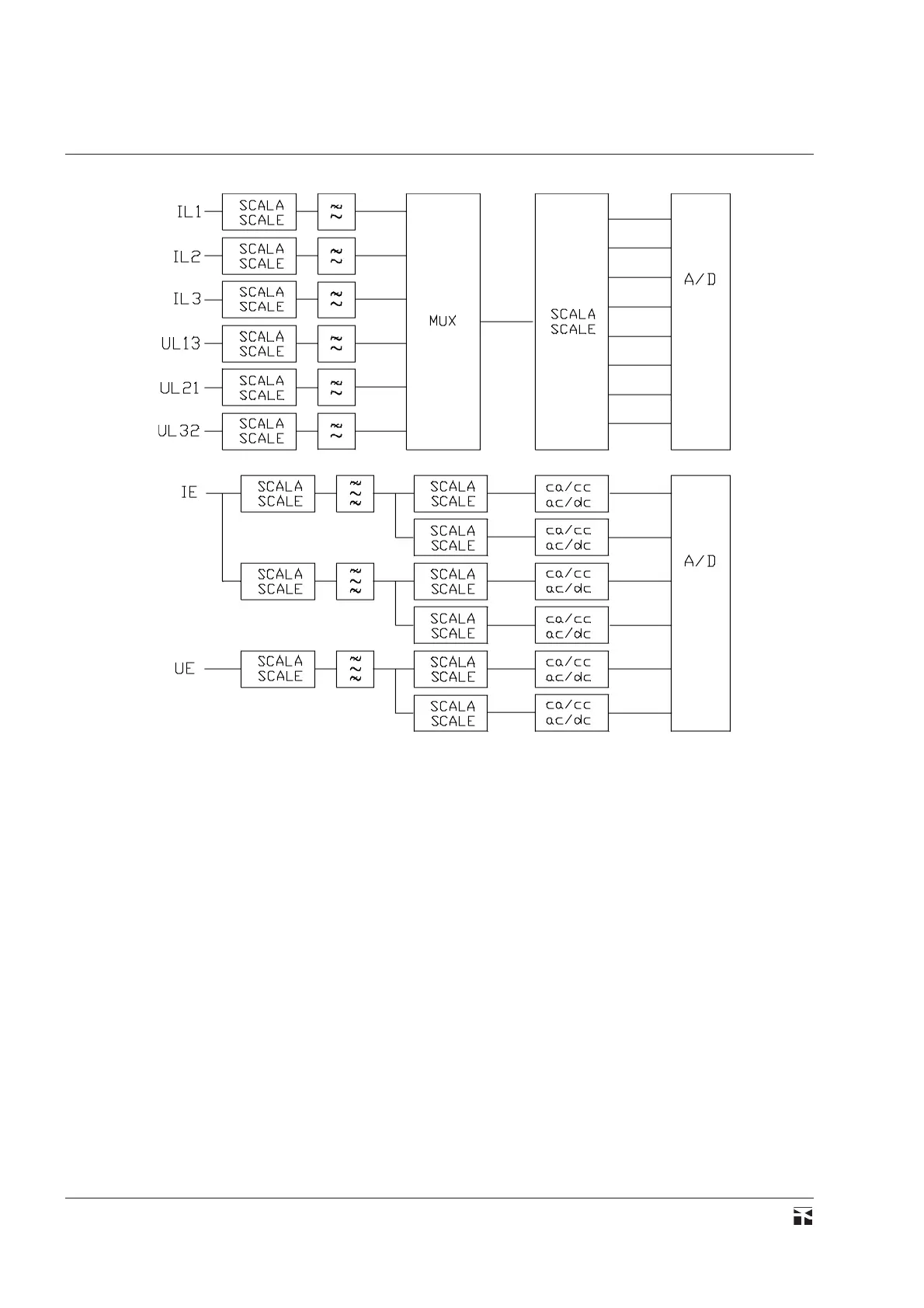
fig.22
 Loading...


