Using the Cylinder Locks
T he loader ar ms may lo w er when in the
raised position cr ushing an y one under them.
Install the cylinder locks bef or e perf or ming
maintenance that r equir es raised loader
ar ms.
Installing the Cylinder Locks
1. Star t the engine .
2. Raise the loader ar ms to the fully raised
position.
3. Stop the engine .
4. P osition a loader ar m cylinder loc k o v er eac h
lift cylinder rod ( Figure 11 ).
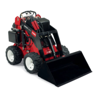
5. Secure eac h loader ar m cylinder loc k with a
clevis pin and cotter pin ( Figure 11 ).
Figure 11
1. Cylinder lock 4. Clevis pin
2. Lift cylinder 5. Lift cylinder rod
3. Hairpin cotter
6. With the engine off , lo w er the loader ar ms .
Removing/Storing the Cylinder Lock
1. Star t the engine .
2. Raise the loader ar ms to the fully raised
position.
3. Stop the engine .
4. R emo v e the clevis pin and cotter pin securing
eac h cylinder loc k.
5. R emo v e the cylinder loc ks .
6. Lo w er the loader ar ms .
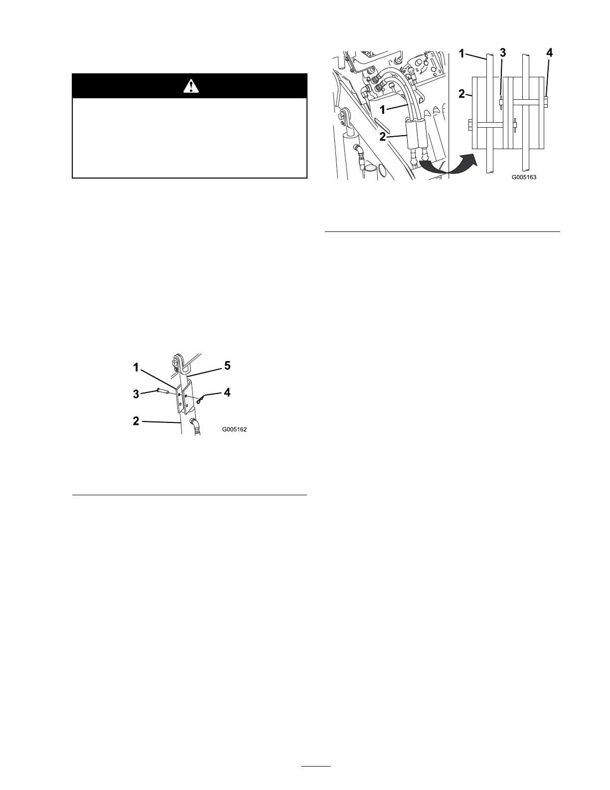
7. Install the cylinder loc ks o v er the h y draulic
hoses and secure them with the clevis pins and
cotter pins ( Figure 12 ).
Figure 12
1. Hydraulic hoses
3. Hairpin cotter
2. Cylinder locks 4. Clevis pin
Using Attachments
Installing an Attachment
Important: Use onl y T or o-appr o v ed
attachments. Attachments can change the
sta bility and the operating characteristics of
the traction unit. T he w ar ranty of the traction
unit may be v oided if used with unappr o v ed
attachments.
Important: Bef or e installing the
attachment, ensur e that the mount plates ar e
fr ee of an y dir t or de bris and that the pins
r otate fr eel y . If the pins do not r otate fr eel y ,
g r ease them.
1. P osition the attac hment on a lev el surface with
enough space behind it to accommodate the
traction unit.
2. Star t the engine .
3. Tilt the attac hment mount plate forw ard.
4. P osition mount plate into the upper lip of the
attac hment recei v er plate ( Figure 13 ).
21
 Loading...