disconnect the c harg er leads from the batter y
posts ( Figure 29 ).
5. R e place the batter y co v er .
Drive System
Maintenance
Servicing the Traction Drive
Chains
Lubricating the Drive Chains
Lubricate the dri v e c hain ev er y 50 operating hours .
1. Lo w er the loader ar ms , stop the engine , and
remo v e the k ey .
2. Apply a g eneral pur pose oil (10W30) onto
upper and lo w er c hain spans .
3. Star t the traction unit and slo wly mo v e it
forw ard to expose unlubed upper and lo w er
c hain spans .
4. Stop the engine and remo v e the k ey .
5. Apply oil to newly exposed unlubed c hain
spans .
Checking the Drive Chain Tension
Chec k the dri v e c hain tension before using the
traction unit for the first time and ev er y 50 hours
of use thereafter .
T he dri v e c hains should ha v e about 1-1/2 to
2-1/2 inc hes (3.8 to 6.35 cm) of slac k betw een the
bottom of the c hain guard and the bottom c hain
span when the top c hain span is pulled tight. Use
the follo wing procedure to c hec k the tension:
1. With the buc k et installed, lo w er it into the
g round until the front tires are off of the
g round.
2. Stop the engine and remo v e the k ey .
3. T ur n the front wheel forw ard on one side of
the traction unit until the top span of the dri v e
c hain is tight.
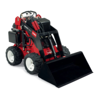
4. Measure the distance betw een the bottom
of the c hain guard and the lo w er c hain span
( Figure 30 ). If the slac k in the c hain is not
within 1-1/2 to 2-1/2 inc hes (3.8 to 6.35
cm), adjust the tension (refer to Adjusting the
T ension).
Figure 30
1. Chain guard 3. 1-1/2 to 2-1/2 inches
2. Bottom span of the chain
5. R e peat ste ps 3 and 4 for the other dri v e c hain.
6. Star t the engine and raise the buc k et to retur n
the front wheels to the g round.
Adjusting the Drive Chain Tension
1. With the buc k et installed, lo w er it into the
g round until the front tires are off of the
g round.
2. Stop the engine and remo v e the k ey .
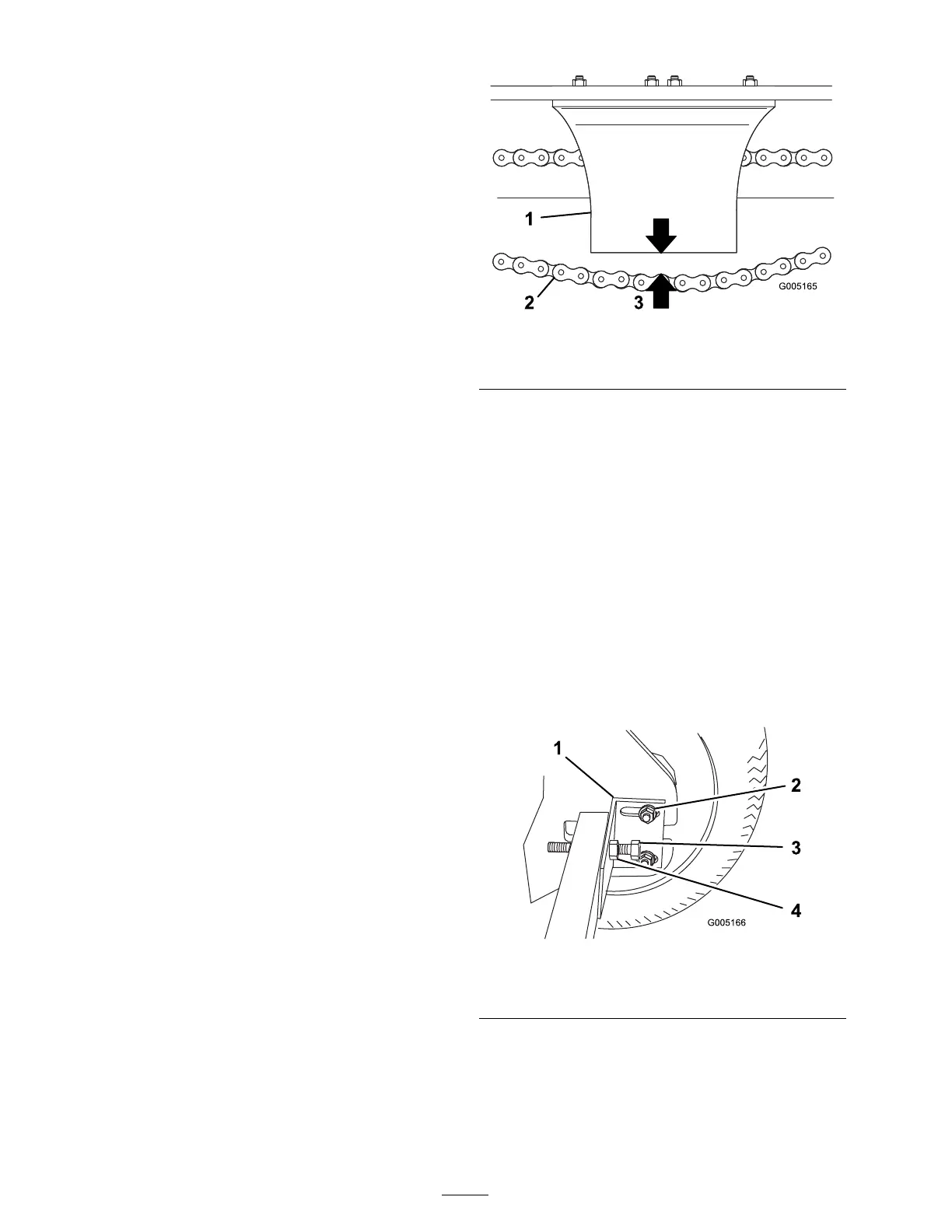
3. Loosen the n uts securing the axle retaining
brac k et ( Figure 31 ).
4. Loosen the n ut on the c hain tensioning bolt
and loosen the bolt ( Figure 31 ).
Figure 31
1. Axle retaining bracket 3. Chain tensioning bolt
2. Nut
4. Nut
5. T ur n the front wheel on one side of the
traction unit until the upper span of the dri v e
c hain is tight.
6. Adjust the c hain tensioning bolt until the
distance betw een the bottom of the c hain
32
 Loading...