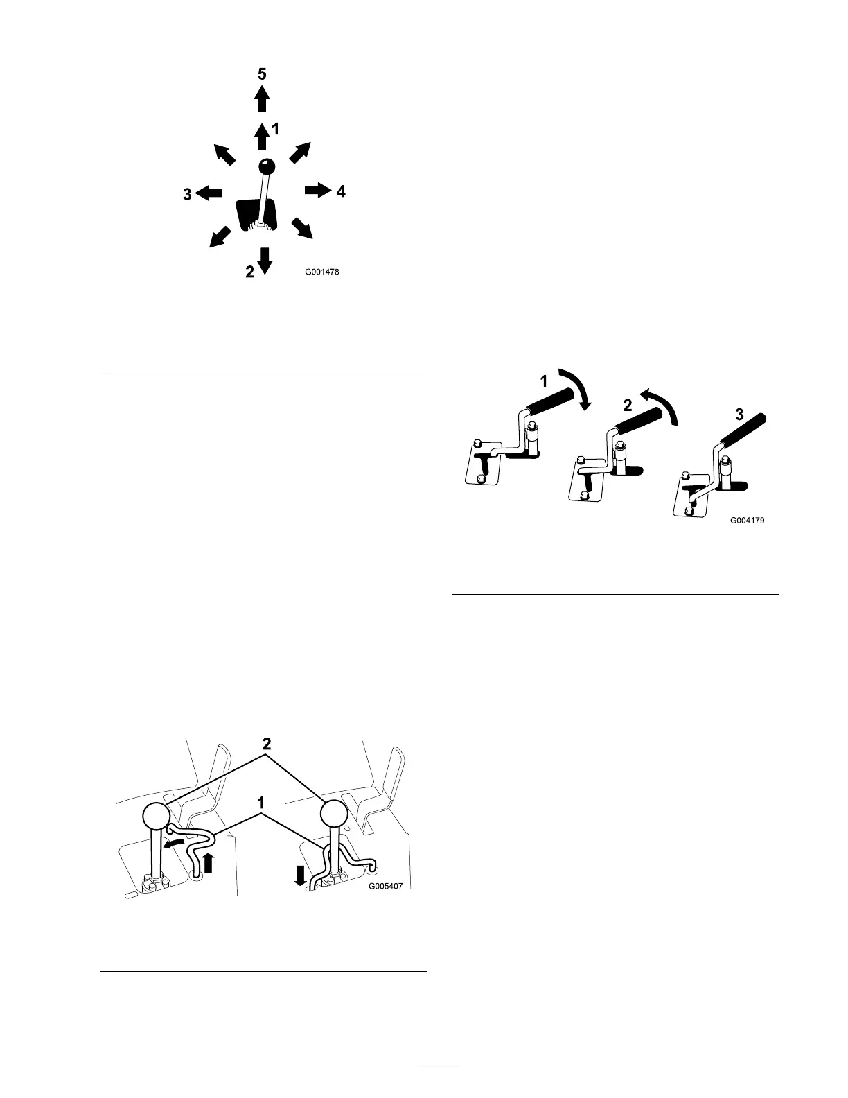
Figure 11
1. Lower the loader arms 4. Tilt the attachment forward
2. Raise the loader arms
5. Detent (Float) position
3. Tilt the attachment
rearward
By mo ving the lev er to an inter mediate position
(suc h as , forw ard and left), y ou can mo v e the
loader ar ms and tilt the attac hment at the same
time .
Loader Valve Lock
T he loader v alv e loc k secures the loader
ar m/attac hment tilt lev er so that y ou cannot push
it forw ard. T his helps to ensure that no one
will accidentally lo w er the loader ar ms during
maintenance . Secure the loader ar ms with the loc k
anytime y ou need to stop the mac hine with the
loader ar ms raised.
T o set the loc k, lift up on it so it clears the hole in
the control panel and swing it to the left in front
of the loader ar m lev er , pushing it do wn into the
loc k ed position ( Figure 12 ).
Figure 12
1. Loader valve lock 2. Loader arm/attachment tilt
lever
Auxiliary Hydraulics Lever
T o operate a h y draulic attac hment in the forw ard
direction, rotate the auxiliar y h y draulics lev er
rearw ard and pull it do wn to the reference bar
( Figure 13 , n umber 1).
T o operate a h y draulic attac hment in rev erse
direction, rotate the h y draulics lev er rearw ard, then
mo v e it left into the upper slot ( Figure 13 , n umber
2).
If y ou release the lev er while in the forw ard
position, the lev er will automatically retur n to the
neutral position ( Figure 13 , n umber 3). If it is in
the rev erse position, it will remain there until y ou
pull it out of the slot.
Figure 13
1. Forward ow hydraulics 3. Neutral
2. Reverse ow hydraulics
Parking Brake Lever
T o set the parking brak e , push the brak e lev er
forw ard and to the left and then pull it rearw ard
( Figure 14 ).
Note: T he traction unit ma y roll slightly before
the brak es eng ag e in the dri v e sproc k et.
17
 Loading...


