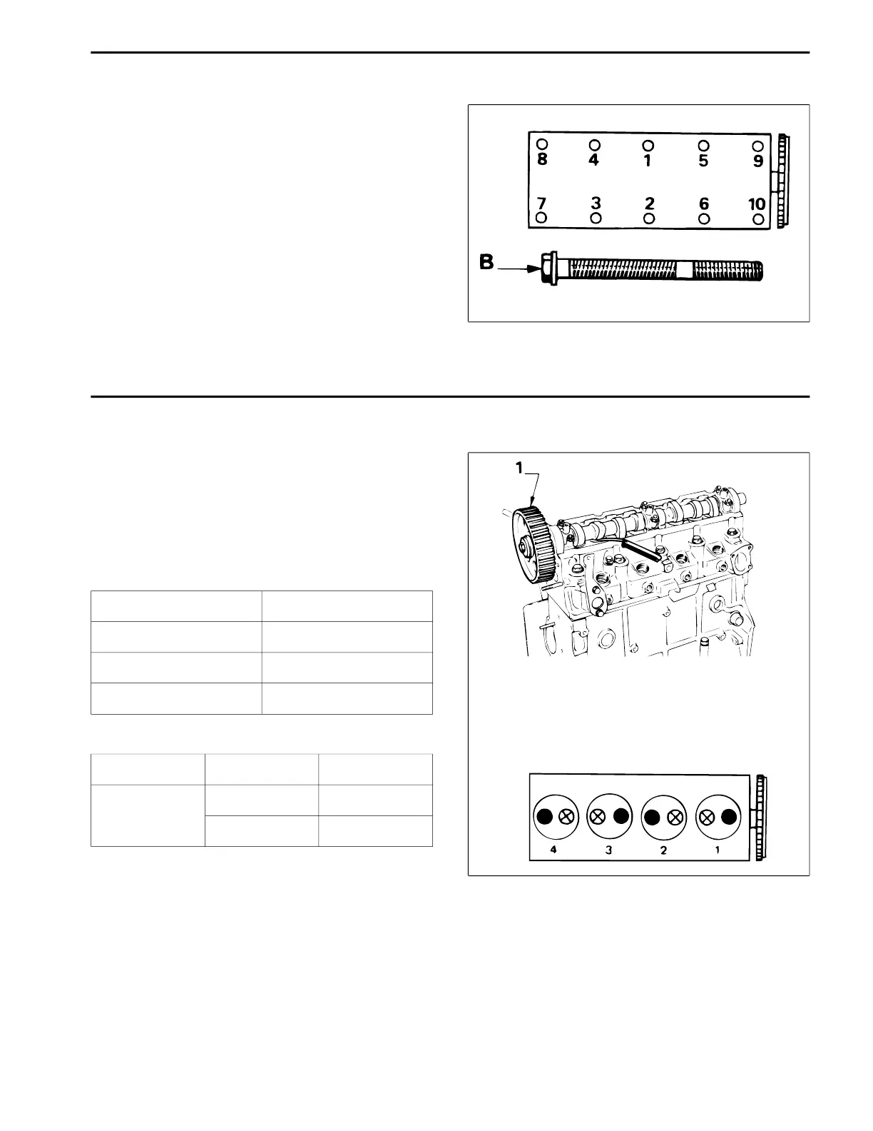
Cylinder Head Tightening
1. Install new washers on the bolts.
2. Pre-tighten the bolts in the order shown (Fig. 84) to a
t
orque of 30 Nm (22 ft-lb).
3. Tighten the bolts in the order shown to a torque of
70 Nm
52 ft-lb).
4. Tighten each bolt in the order shown an additional
120° ± 2°.
NOTE: The special cylinder head bolts (Item B) do not
require re-tightening. The bolts can be removed and
re-installed 5 times before replacing with new bolts.
Valve Clearance Adjustment
NOTE: If all valve parts are re-installed in their original
location it should not be necessary to adjust valve
clearance, unless the head has been machined or val-
ves ground.
1. Install the camshaft gear. (Fig. 85, Item 1).
2. Check the valve clearance:
Units: mm
Running Clearance
Inlet 0.15
Exhaust 0.30
Tolerance ± 0.
04
Set “on the rock” Inlet 4, Exhaust 4 Inlet 1, Exhaust 1
Check Inlet 1, Exhaust 1 Inlet 4, Exhaust 4
Inlet 2, Exhaust 3 Inlet 3, Exhaust 2
Figure 84
Figure 85
Reelmaster 335-D/3500-D Page 3 - 57
Rev. B
Engine

 Loading...