2.Installthepositive(red)batterycabletothepositive
(+)batteryterminalusingthefastenersremoved
previously
3.Installthenegativebatterycabletothenegative
(-)batteryterminalusingthefastenersremoved
previously.
4.Slidetheredterminalbootontothepositive(red)
batterypost.
5.Securethebatterywiththehold-down(Figure32).
ServicingtheFusesandRelay
Theelectricalsystemisprotectedbyfuses.Itrequires
nomaintenance;however,ifafuseblows,checkthe
component/circuitforamalfunctionorshort.Thereis
alsoareplaceablerelay/snexttothefuse.Refertoyour
Partsmanualforcorrectreplacementcomponents.
Fuse:Block:
•Main:25ampfuse,blade-type
•ChargeCircuit:20ampfuse,blade-type
•Auxiliarycircuit:15ampfuse,blade-type
•Diode:TVS
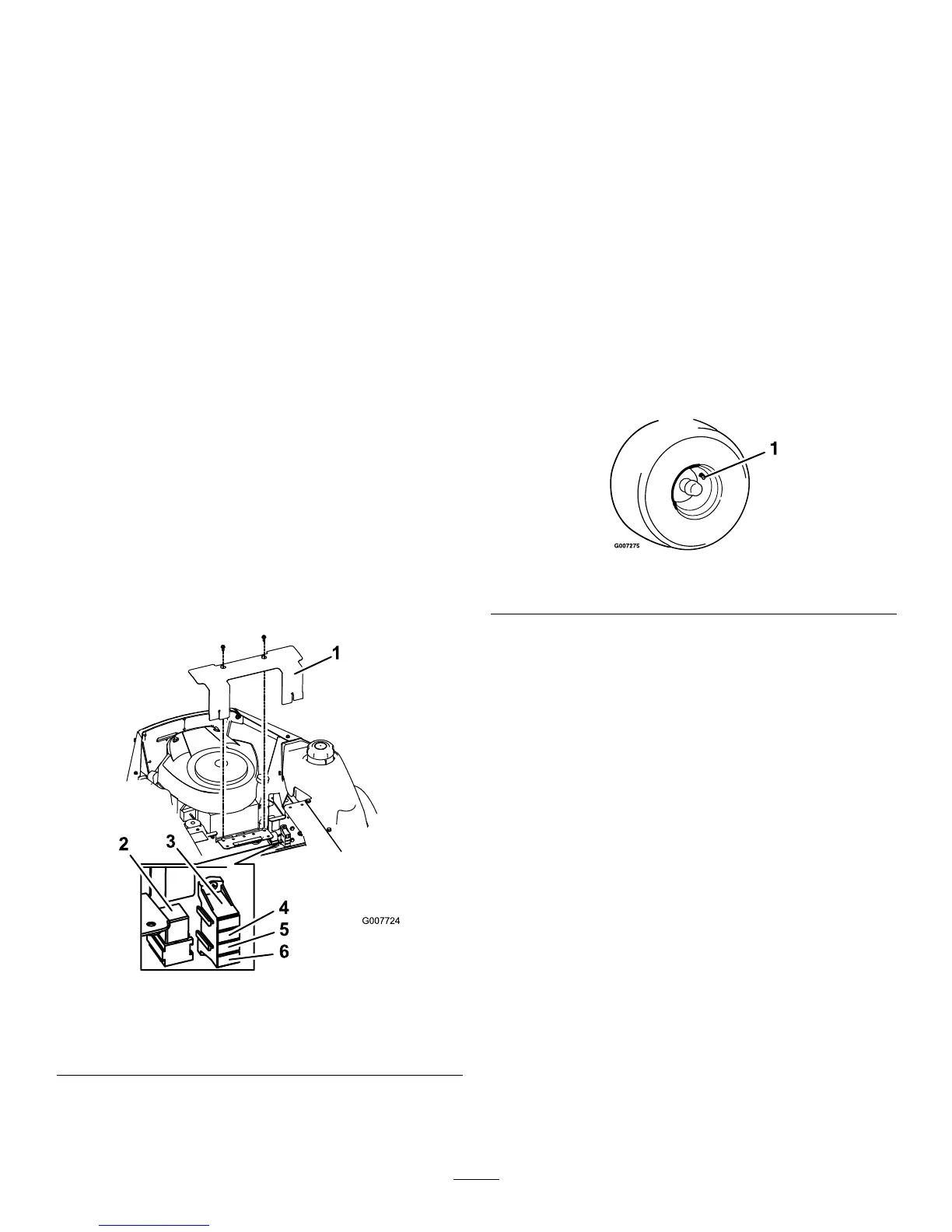
1.Raisetheseattogainaccesstothefuseholder
(Figure34).
Figure34
1.Cover4.Charge–20amp
2.Relay5.Main–25amp
3.Auxilliary–15amp6.Diode
2.RemovecoverasshowninFigure34.
3.Toreplaceafuse,pulloutonthefusetoremoveit
DriveSystem
Maintenance
CheckingtheTirePressure
ServiceInterval:Every25hours/Monthly(whichever
comesrst)
Maintaintheairpressureinthefrontandreartiresas
specied.Uneventirepressurecancauseunevencut.
Checkthepressureatthevalvestem(Figure35).
Checkthetireswhentheyarecoldtogetthemost
accuratepressurereading.
RearTires:13psi(90kPa)
FrontTires(casterwheels):13psi(90kPa)
Figure35
1.Valvestem
35
 Loading...