g336998
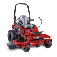
Figure 84
1. Access holes for the vent plugs
• For ZT 5400 Hydros , use a 7/16-inch wrench
to access the vent plug from underneath the
machine ( Figure 85 ).
g336999
Figure 85
1. V ent plug
5. Carefully clean the area around the lter .
Important: Do not allow dirt to enter the
hydraulic system; otherwise, contamination
may occur .
6. Place a drain pan below the lter to catch the
uid that drains when the lter and vent plugs
are removed.
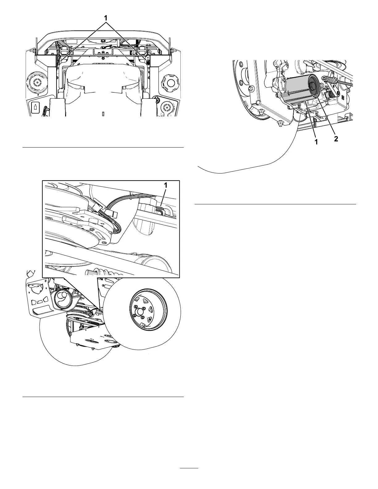
7. Remove the hydraulic-uid lter cover from the
transaxle to drain the uid ( Figure 86 ).
g334915
Figure 86
1. Hydraulic-lter housing 2. Cover
8. Remove the O-ring from the lter cover and
discard the O-ring.
9. After the hydraulic uid drains from the transaxle,
remove the lter from the transaxle housing.
10. Repeat this procedure on the other side of the
machine.
Installing the Hydraulic Fluid and
Filters
1. Install a new lter in the transaxle and a new
O-ring onto the lter cover .
2. Install the lter cover .
3. T orque the lter cover as follows:
• ZT 4400 Hydros: 22.6 to 33.8 N∙m (200 to
300 in-lb)
• ZT 5400 Hydros: 54.3 to 65.5 N∙m (480 to
580 in-lb)
4. Remove the cap from the expansion tank and ll
the transaxles with the specied uid until the
proper uid capacities are met.
Note: Filling the transaxles may take more time
than expected.
5. Install the previously removed vent plugs and
torque the plugs to 395 to 904 N∙cm (35 to 80
in-lb).
6. Proceed to Bleeding the Hydraulic System
( page 65 ) .
64
 Loading...

